Three Winding Transformer
Create Function
- pandapower.create.create_transformer3w(net, hv_bus, mv_bus, lv_bus, std_type, name=None, tap_pos=nan, in_service=True, index=None, max_loading_percent=nan, tap_changer_type=None, tap_at_star_point=False, tap_dependency_table=False, id_characteristic_table=None, **kwargs)
Creates a three-winding transformer in table net.trafo3w. The trafo parameters are defined through the standard type library.
- Parameters:
net (pandapowerNet) – the net within this transformer should be created
hv_bus (int | integer) – The bus on the high-voltage side on which the transformer will be connected to
mv_bus (int | integer) – The medium voltage bus on which the transformer will be connected to
lv_bus (int | integer) – The bus on the low-voltage side on which the transformer will be connected to
std_type (str) – the used standard type from the standard type library
name (str | None) – a custom name for this transformer
tap_pos (int | float) – current tap position of the transformer. Defaults to the medium position (tap_neutral)
tap_changer_type (Literal['Ratio', 'Symmetrical', 'Ideal', 'Tabular'] | None) – specifies the tap changer type (“Ratio”, “Symmetrical”, “Ideal”, “Tabular”, None: no tap changer)*
tap_at_star_point (bool) – whether tap changer is located at the star point of the 3w-transformer or at the bus
in_service (bool) – True for in_service or False for out of service
index (int | integer | None) – force a specified ID if it is available. If None, the index one higher than the highest already existing index is selected.
max_loading_percent (float) – maximum current loading (only needed for OPF)
tap_at_star_point – whether tap changer is modelled at star point or at the bus
tap_dependency_table (bool) – True if transformer parameters (voltage ratio, angle, impedance) must be adjusted dependent on the tap position of the transformer. Requires the additional column “id_characteristic_table”. The function pandapower.control.trafo_characteristic_table_diagnostic can be used for sanity checks. The function pandapower.control.create_trafo_characteristic_object can be used to create SplineCharacteristic objects in the net.trafo_characteristic_spline table and add the additional column “id_characteristic_spline” to set up the reference to the spline characteristics.
id_characteristic_table (int | None) – references the index of the characteristic from the lookup table net.trafo_characteristic_table
- Returns:
The ID of the created transformer
- Return type:
int | integer
Example
>>> create_transformer3w(net, hv_bus=0, mv_bus=1, lv_bus=2, name="trafo1", std_type="63/25/38 MVA 110/20/10 kV")
- pandapower.create.create_transformers3w(net, hv_buses, mv_buses, lv_buses, std_type, tap_pos=nan, name=None, in_service=True, index=None, max_loading_percent=nan, tap_at_star_point=False, tap_changer_type=None, tap_dependency_table=False, id_characteristic_table=None, **kwargs)
Creates several two-winding transformers in table net.trafo. Additional parameters passed will be added to the transformers dataframe. If keywords are passed that are present in the std_type they will override any setting from the standard type.
- Parameters:
net (pandapowerNet) – the pandapower network to which the transformers should be added
hv_buses (Sequence) – a Sequence of bus ids that are the high voltage buses for the transformers
mv_buses (Sequence) – a Sequence of bus ids that are the medium voltage buses for the transformers
lv_buses (Sequence) – a Sequence of bus ids that are the low valtage buses for the transformers
std_type (str) – the transformer std_type to get the not specified parameters from
tap_pos (int | Iterable[int] | float) – current tap position of the transformers. Defaults to the medium position (tap_neutral), default nan
name (Iterable[str] | None) – names for the transformers, default None
in_service (bool | Iterable[bool]) – Wheather the transforers are in or out of service, default True
index (Iterable[int | integer] | None) – the index to use for the new elements, default None
max_loading_percent (float | Iterable[float]) – the maximum loading percentage of the transformer, default nan
tap_at_star_point (bool | Iterable[bool]) – whether tap changer is modelled at star point or at the bus
tap_changer_type (float | Iterable[float] | None) – specifies the phase shifter type (“Ratio”, “Symmetrical”, “Ideal”, “Tabular” or None), default None
tap_dependency_table (bool | Iterable[bool]) – True if sanity checks should be performed. See SplineCharacteristics, default False
id_characteristic_table (int | Iterable[int] | None) – id of the SplineCharacteristic, default None
- Return type:
ndarray[tuple[Any, …], dtype[int | integer]]
Example
>>> create_transformers3w(
>>>     net, hv_bus=[0, 1], lv_bus=[2, 3], std_type="63/25/38 MVA 110/20/10 kV", name=["trafo1", "trafo2"]
>>> )
- pandapower.create.create_transformer3w_from_parameters(net, hv_bus, mv_bus, lv_bus, vn_hv_kv, vn_mv_kv, vn_lv_kv, sn_hv_mva, sn_mv_mva, sn_lv_mva, vk_hv_percent, vk_mv_percent, vk_lv_percent, vkr_hv_percent, vkr_mv_percent, vkr_lv_percent, pfe_kw, i0_percent, shift_mv_degree=0.0, shift_lv_degree=0.0, tap_side=None, tap_step_percent=nan, tap_step_degree=nan, tap_pos=nan, tap_neutral=nan, tap_max=nan, tap_changer_type=None, tap_min=nan, name=None, in_service=True, index=None, max_loading_percent=nan, tap_at_star_point=False, vk0_hv_percent=nan, vk0_mv_percent=nan, vk0_lv_percent=nan, vkr0_hv_percent=nan, vkr0_mv_percent=nan, vkr0_lv_percent=nan, vector_group=None, tap_dependency_table=False, id_characteristic_table=None, **kwargs)
Adds a three-winding transformer in table net.trafo3w with the specified parameters. The model currently only supports one tap changer per 3w-transformer.
- Parameters:
net (pandapowerNet) – the net within this transformer should be created
hv_bus (int | integer) – the bus on the high-voltage side on which the transformer will be connected to
mv_bus (int | integer) – The bus on the middle-voltage side on which the transformer will be connected to
lv_bus (int | integer) – The bus on the low-voltage side on which the transformer will be connected to
vn_hv_kv (float) – rated voltage on high voltage side
vn_mv_kv (float) – rated voltage on medium voltage side
vn_lv_kv (float) – rated voltage on low voltage side
sn_hv_mva (float) – rated apparent power on high voltage side
sn_mv_mva (float) – rated apparent power on medium voltage side
sn_lv_mva (float) – rated apparent power on low voltage side
vk_hv_percent (float) – short circuit voltage from high to medium voltage
vk_mv_percent (float) – short circuit voltage from medium to low voltage
vk_lv_percent (float) – short circuit voltage from high to low voltage
vkr_hv_percent (float) – real part of short circuit voltage from high to medium voltage
vkr_mv_percent (float) – real part of short circuit voltage from medium to low voltage
vkr_lv_percent (float) – real part of short circuit voltage from high to low voltage
pfe_kw (float) – iron losses in kW
i0_percent (float) – open loop losses
shift_mv_degree (float) – angle shift to medium voltage side*
shift_lv_degree (float) – angle shift to low voltage side*
tap_step_percent (float) – tap step in percent
tap_step_degree (float) – tap phase shift angle in degrees
tap_side (Literal['hv', 'mv', 'lv'] | None) – “hv”, “mv”, “lv”
tap_neutral (int | float) – default tap position
tap_min (float | None) – Minimum tap position
tap_max (int | float) – Maximum tap position
tap_pos (int | float) – current tap position of the transformer. Defaults to the medium position (tap_neutral)
tap_changer_type (Literal['Ratio', 'Symmetrical', 'Ideal', 'Tabular'] | None) – specifies the tap changer type (“Ratio”, “Symmetrical”, “Ideal”, “Tabular”, None: no tap changer)
tap_at_star_point (bool) – Whether tap changer is located at the star point of the 3w-transformer or at the bus
name (str | None) – name of the 3-winding transformer
in_service (bool) – True for in_service or False for out of service
max_loading_percent (float) – maximum current loading (only needed for OPF)
tap_dependency_table (bool) – True if transformer parameters (voltage ratio, angle, impedance) must be adjusted dependent on the tap position of the transformer. Requires the additional column “id_characteristic_table”. The function pandapower.control.trafo_characteristic_table_diagnostic can be used for sanity checks. The function pandapower.control.create_trafo_characteristic_object can be used to create SplineCharacteristic objects in the net.trafo_characteristic_spline table and add the additional column “id_characteristic_spline” to set up the reference to the spline characteristics.
id_characteristic_table (int | None) – references the index of the characteristic from the lookup table net.trafo_characteristic_table
vk0_hv_percent (float) – zero sequence short circuit voltage from high to medium voltage
vk0_mv_percent (float) – zero sequence short circuit voltage from medium to low voltage
vk0_lv_percent (float) – zero sequence short circuit voltage from high to low voltage
vkr0_hv_percent (float) – zero sequence real part of short circuit voltage from high to medium voltage
vkr0_mv_percent (float) – zero sequence real part of short circuit voltage from medium to low voltage
vkr0_lv_percent (float) – zero sequence real part of short circuit voltage from high to low voltage
vector_group (str | None) – vector group of the 3w-transformer
index (int | integer | None)
- Returns:
The ID of the created 3w-transformer
- Return type:
int | integer
Example
>>> create_transformer3w_from_parameters(
>>>     net, hv_bus=0, mv_bus=1, lv_bus=2, name="trafo1", sn_hv_mva=40, sn_mv_mva=20, sn_lv_mva=20,
>>>     vn_hv_kv=110, vn_mv_kv=20, vn_lv_kv=10, vk_hv_percent=10,vk_mv_percent=11, vk_lv_percent=12,
>>>     vkr_hv_percent=0.3, vkr_mv_percent=0.31, vkr_lv_percent=0.32, pfe_kw=30, i0_percent=0.1,
>>>     shift_mv_degree=30, shift_lv_degree=30
>>> )
- pandapower.create.create_transformers3w_from_parameters(net, hv_buses, mv_buses, lv_buses, vn_hv_kv, vn_mv_kv, vn_lv_kv, sn_hv_mva, sn_mv_mva, sn_lv_mva, vk_hv_percent, vk_mv_percent, vk_lv_percent, vkr_hv_percent, vkr_mv_percent, vkr_lv_percent, pfe_kw, i0_percent, shift_mv_degree=0.0, shift_lv_degree=0.0, tap_side=None, tap_step_percent=nan, tap_step_degree=nan, tap_pos=nan, tap_neutral=nan, tap_max=nan, tap_min=nan, name=None, in_service=True, index=None, max_loading_percent=nan, tap_at_star_point=False, tap_changer_type=None, vk0_hv_percent=nan, vk0_mv_percent=nan, vk0_lv_percent=nan, vkr0_hv_percent=nan, vkr0_mv_percent=nan, vkr0_lv_percent=nan, vector_group=None, tap_dependency_table=False, id_characteristic_table=None, **kwargs)
Adds multiple three-winding transformers in table net.trafo3w with the specified parameters. The model currently only supports one tap changer per 3w-transformer.
- Parameters:
net (pandapowerNet) – the net within this transformer should be created
hv_bus – The bus on the high-voltage side on which the transformer will be connected to
mv_bus – The bus on the middle-voltage side on which the transformer will be connected to
lv_bus – The bus on the low-voltage side on which the transformer will be connected to
vn_hv_kv (float | Iterable[float]) – rated voltage on high voltage side
vn_mv_kv (float | Iterable[float]) – rated voltage on medium voltage side
vn_lv_kv (float | Iterable[float]) – rated voltage on low voltage side
sn_hv_mva (float | Iterable[float]) – rated apparent power on high voltage side
sn_mv_mva (float | Iterable[float]) – rated apparent power on medium voltage side
sn_lv_mva (float | Iterable[float]) – rated apparent power on low voltage side
vk_hv_percent (float | Iterable[float]) – short circuit voltage from high to medium voltage
vk_mv_percent (float | Iterable[float]) – short circuit voltage from medium to low voltage
vk_lv_percent (float | Iterable[float]) – short circuit voltage from high to low voltage
vkr_hv_percent (float | Iterable[float]) – real part of short circuit voltage from high to medium voltage
vkr_mv_percent (float | Iterable[float]) – real part of short circuit voltage from medium to low voltage
vkr_lv_percent (float | Iterable[float]) – real part of short circuit voltage from high to low voltage
pfe_kw (float | Iterable[float]) – iron losses in kW
i0_percent (float | Iterable[float]) – open loop losses
shift_mv_degree (float | Iterable[float]) – angle shift to medium voltage side*
shift_lv_degree (float | Iterable[float]) – angle shift to low voltage side*
tap_step_percent (float | Iterable[float]) – tap step in percent
tap_step_degree (float | Iterable[float]) – tap phase shift angle in degrees*
tap_side (Literal['hv', 'mv', 'lv'] | ~typing.Iterable[str] | None) – “hv”, “mv”, “lv”
tap_neutral (int | Iterable[int] | float) – default tap position
tap_min (int | Iterable[int] | float) – minimum tap position
tap_max (int | Iterable[int] | float) – maximum tap position
tap_pos (int | Iterable[int] | float) – current tap position of the transformer. Defaults to the medium position (tap_neutral)
tap_changer_type (float | Iterable[float] | None) – specifies the tap changer type (“Ratio”, “Symmetrical”, “Ideal”, “Tabular”, None: no tap changer)*
tap_at_star_point (bool | Iterable[bool]) – whether tap changer is located at the star point of the 3w-transformer or at the bus
name (Iterable[str] | None) – name of the 3-winding transformer
in_service (bool | Iterable[bool]) – True for in_service or False for out of service
max_loading_percent (float | Iterable[float]) – maximum current loading (only needed for OPF)
tap_dependency_table (bool | Iterable[bool]) – True if transformer parameters (voltage ratio, angle, impedance) must be adjusted dependent on the tap position of the transformer. Requires the additional column “id_characteristic_table”. The function pandapower.control.trafo_characteristic_table_diagnostic can be used for sanity checks. The function pandapower.control.create_trafo_characteristic_object can be used to create SplineCharacteristic objects in the net.trafo_characteristic_spline table and add the additional column “id_characteristic_spline” to set up the reference to the spline characteristics.
id_characteristic_table (int | Iterable[int] | None) – references the index of the characteristic from the lookup table net.trafo_characteristic_table
vk0_hv_percent (float | Iterable[float]) – zero sequence short circuit voltage from high to medium voltage
vk0_mv_percent (float | Iterable[float]) – zero sequence short circuit voltage from medium to low voltage
vk0_lv_percent (float | Iterable[float]) – zero sequence short circuit voltage from high to low voltage
vkr0_hv_percent (float | Iterable[float]) – zero sequence real part of short circuit voltage from high to medium voltage
vkr0_mv_percent (float | Iterable[float]) – zero sequence real part of short circuit voltage from medium to low voltage
vkr0_lv_percent (float | Iterable[float]) – zero sequence real part of short circuit voltage from high to low voltage
vector_group (str | Iterable[str] | None) – vector group of the 3w-transformers
hv_buses (Sequence)
mv_buses (Sequence)
lv_buses (Sequence)
index (Iterable[int | integer] | None)
- Returns:
list of ids of the created 3w-transformers
- Return type:
ndarray[tuple[Any, …], dtype[integer]]
Example
>>> create_transformers3w_from_parameters(
>>>     net, hv_bus=[0, 3], mv_bus=[1, 4], lv_bus=[2, 5], name="trafo1", sn_hv_mva=40, sn_mv_mva=20,
>>>     sn_lv_mva=20, vn_hv_kv=110, vn_mv_kv=20, vn_lv_kv=10, vk_hv_percent=10,vk_mv_percent=11,
>>>     vk_lv_percent=12, vkr_hv_percent=0.3, vkr_mv_percent=0.31, vkr_lv_percent=0.32, pfe_kw=30,
>>>     i0_percent=0.1, shift_mv_degree=30, shift_lv_degree=30
>>> )
* only considered in load flow if calculate_voltage_angles = True
Note
All short circuit voltages are given relative to the minimum apparent power flow. For example vk_hv_percent is the short circuit voltage from the high to the medium level, it is given relative to the minimum of the rated apparent power in high and medium level: min(sn_hv_mva, sn_mv_mva). This is consistent with most commercial network calculation software (e.g. PowerFactory). Some tools (like PSS Sincal) however define all short circuit voltages relative to the overall rated apparent power of the transformer: max(sn_hv_mva, sn_mv_mva, sn_lv_mva). You might have to convert the values depending on how the short-circuit voltages are defined.
Input Parameters
net.trafo3w
Parameter |
Datatype |
Value Range |
Explanation |
name |
string |
name of the transformer |
|
std_type |
string |
transformer standard type name |
|
hv_bus* |
integer |
high voltage bus index of the transformer |
|
mv_bus |
integer |
medium voltage bus index of the transformer |
|
lv_bus* |
integer |
low voltage bus index of the transformer |
|
vn_hv_kv* |
float |
rated voltage at high voltage bus [kV] |
|
vn_mv_kv* |
float |
\(>\) 0 |
rated voltage at medium voltage bus [kV] |
vn_lv_kv* |
float |
\(>\) 0 |
rated voltage at low voltage bus [kV] |
sn_hv_mva* |
float |
\(>\) 0 |
rated apparent power on high voltage side [kVA] |
sn_mv_mva* |
float |
\(>\) 0 |
rated apparent power on medium voltage side [kVA] |
sn_lv_mva* |
float |
\(>\) 0 |
rated apparent power on low voltage side [kVA] |
vk_hv_percent* |
float |
\(>\) 0 |
short circuit voltage from high to medium voltage [%] |
vk_mv_percent* |
float |
\(>\) 0 |
short circuit voltage from medium to low voltage [%] |
vk_lv_percent* |
float |
\(>\) 0 |
short circuit voltage from high to low voltage [%] |
vkr_hv_percent* |
float |
\(\geq\) 0 |
real part of short circuit voltage from high to medium voltage [%] |
vkr_mv_percent* |
float |
\(\geq\) 0 |
real part of short circuit voltage from medium to low voltage [%] |
vkr_lv_percent* |
float |
\(\geq\) 0 |
real part of short circuit voltage from high to low voltage [%] |
pfe_kw* |
float |
\(\geq\) 0 |
iron losses [kW] |
i0_percent* |
float |
\(\geq\) 0 |
open loop losses [%] |
shift_mv_degree |
float |
transformer phase shift angle at the MV side |
|
shift_lv_degree |
float |
transformer phase shift angle at the LV side |
|
tap_side |
string |
“hv”, “mv”, “lv” |
defines if tap changer is positioned on high- medium- or low voltage side |
tap_neutral |
integer |
||
tap_min |
integer |
minimum tap position |
|
tap_max |
integer |
maximum tap position |
|
tap_step_percent |
float |
\(>\) 0 |
tap step size [%] |
tap_step_degree |
float |
tap step size for voltage angle |
|
tap_at_star_point |
boolean |
True / False |
whether the tap changer is modelled at terminal or at star point |
tap_pos |
integer |
current position of tap changer |
|
tap_changer_type |
string |
“Ratio”, “Symmetrical”, “Ideal”, “Tabular” |
specifies the tap changer type |
tap_dependency_table |
boolean |
True / False |
whether the transformer parameters (voltage ratio, angle, impedance) are adjusted dependent on the tap position of the transformer |
id_characteristic_table |
integer |
\(\geq\) 0 |
references the id_characteristic index from the trafo_characteristic_table |
in_service* |
boolean |
True / False |
specifies if the transformer is in service. |
*necessary for executing a power flow calculation.
Note
Three Winding Transformer loading can not yet be constrained with the optimal power flow.
Electric Model
Three Winding Transformers are modelled by three two-winding transformers in \(Y\)-connection:
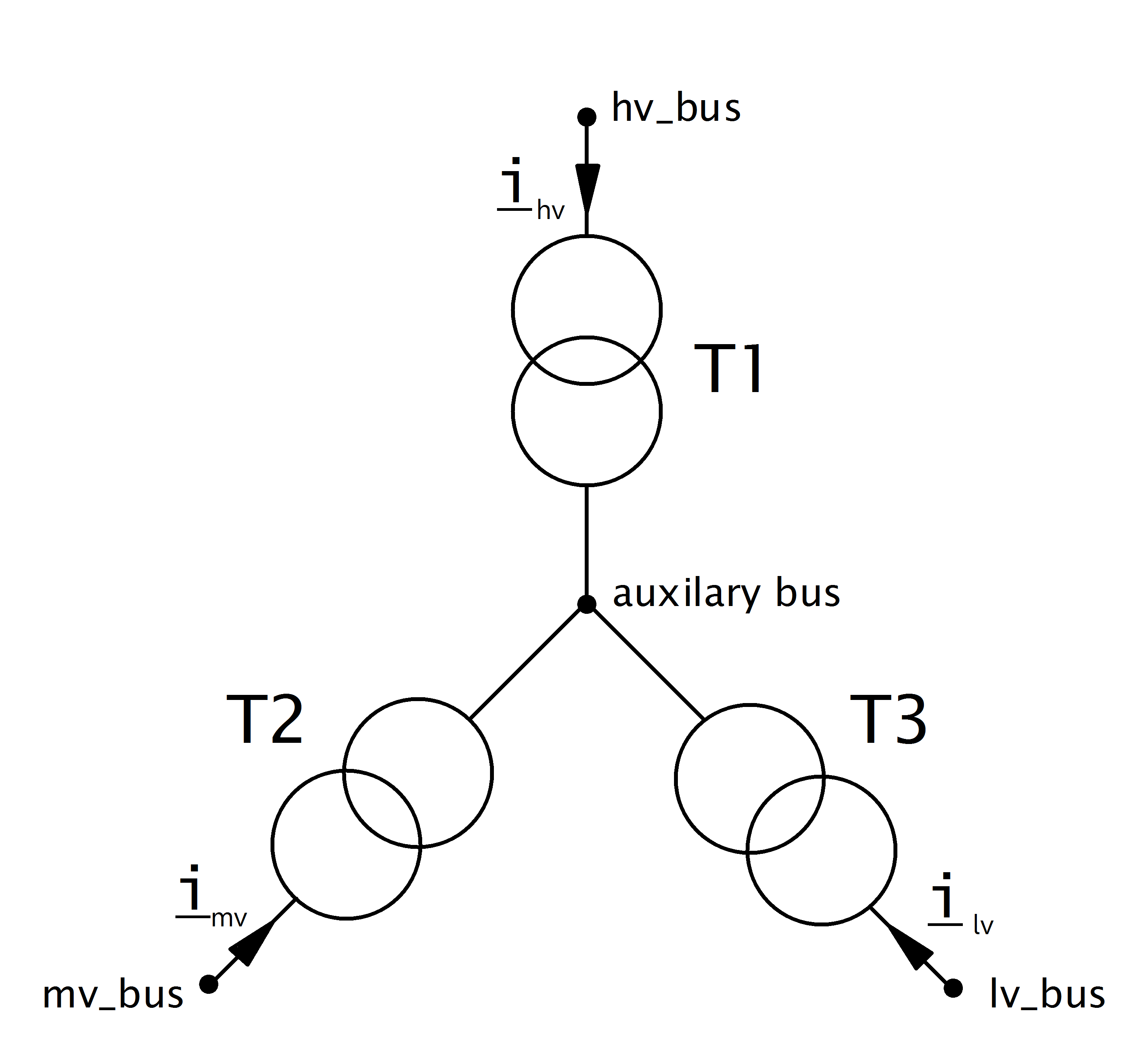
The parameters of the three transformers are defined as follows:
T1 |
T2 |
T3 |
|
hv_bus |
hv_bus |
auxiliary bus |
auxiliary bus |
lv_bus |
auxiliary bus |
mv_bus |
lv_bus |
sn_mva |
sn_hv_mva |
sn_mv_mva |
sn_lv_mva |
vn_hv_kv |
vn_hv_kv |
vn_hv_kv |
vn_hv_kv |
vn_lv_kv |
vn_hv_kv |
vn_mv_kv |
vn_lv_kv |
vk_percent |
\(v_{k, t1}\) |
\(v_{k, t2}\) |
\(v_{k, t3}\) |
vkr_percent |
\(v_{r, t1}\) |
\(v_{r, t2}\) |
\(v_{r, t3}\) |
shift_degree |
0 |
shift_mv_degree |
shift_lv_degree |
The iron loss (pfe_kw) and open loop loss (i0_percent) of the 3W transformer is by default attributed to T1 (‘hv’). The parameter ‘trafo3w_losses’ in the runpp function however also allows to assign the losses to T2 (‘mv’), T3(‘lv’) or to the star point (‘star’).
To calculate the short-circuit voltages \(v_{k, t1..t3}\) and \(v_{r, t1..t3}\), first all short-circuit voltages are converted from side based values to branch based values
These transformer now represent a \(\Delta\) connection of the equivalent transformers. A \(\Delta-Y\) conversion is therefore applied to receive the parameters in \(Y\)-connection:
Since these voltages are given relative to the high voltage side, they have to be transformed back to the voltage level of each transformer:
The real part of the short-circuit voltage is calculated in the same way.
The definition of how impedance’s are calculated for the two winding transformer from these parameters can be found here.
Note
All short circuit voltages are given relative to the maximum apparent power flow. For example vk_hv_percent is the short circuit voltage from the high to the medium level, it is given relative to the minimum of the rated apparent power in high and medium level: min(sn_hv_mva, sn_mv_mva). This is consistent with most commercial network calculation software (e.g. PowerFactory). Some tools (like PSS Sincal) however define all short circuit voltages relative to the overall rated apparent power of the transformer: max(sn_hv_mva, sn_mv_mva, sn_lv_mva). You might have to convert the values depending on how the short-circuit voltages are defined.
The tap changer adapts the nominal voltages of the transformer in the equivalent to the 2W-Model:
tap_side=”hv” |
tap_side=”mv” |
tap_side=”lv” |
|
\(V_{n, HV, transformer}\) |
\(vnh\_kv \cdot n_{tap}\) |
\(vnh\_kv\) |
\(vnh\_kv\) |
\(V_{n, MV, transformer}\) |
\(vnm\_kv\) |
\(vnm\_kv \cdot n_{tap}\) |
\(vnm\_kv\) |
\(V_{n, LV, transformer}\) |
\(vnl\_kv\) |
\(vnl\_kv\) |
\(vnl\_kv \cdot n_{tap}\) |
with
The variable tap_side controls if the tap changer is located at T1 (‘hv’), T2 (‘mv’) or T3 (‘lv’). The tap_at_star_point variable controls if the tap changer is located at the star point of the three winding transformer or at the terminal side (hv/mv/lv bus).
See also
Trafo characteristic table
A transformer characteristic table (trafo_characteristic_table) can be used to adjust the 3-winding transformer parameters (voltage ratio, angle, impedance) according to the selected tap position. This lookup table is created automatically from version 3.0 onwards through the CIM CGMES to pandapower converter (if this information is available in the EQ profile), or the user may define this table manually. The id_characteristic_table variable in net.trafo3w references the id_characteristic column in net.trafo_characteristic_table per 3-winding transformer.
If the tap_dependency_table variable in net.trafo3w is set to True, this indicates that there is a corresponding characteristic available in net.trafo_characteristic_table, which overwrites the default 3-winding transformer parameters tap_step_percent, tap_step_degree, vkr_hv_percent, vkr_mv_percent, vkr_lv_percent, vk_hv_percent, vk_mv_percent and vk_lv_percent.
The below table provides an example trafo_characteristic_table, populated for two 3-winding transformers.
id_characteristic |
step |
voltage_ratio |
angle_deg |
vk_percent |
vkr_percent |
vkr_hv_percent |
vkr_mv_percent |
vkr_lv_percent |
vk_hv_percent |
vk_mv_percent |
vk_lv_percent |
|
0 |
0 |
10 |
1.049230814 |
0 |
0.202038469 |
0.151000013 |
0.169759643 |
19.50770312 |
7.0000001 |
12.62692044 |
||
1 |
0 |
11 |
1.036923051 |
0 |
0.202278839 |
0.151000013 |
0.169819736 |
19.38077652 |
7.0000001 |
12.59519014 |
||
2 |
0 |
12 |
1.024615407 |
0 |
0.20251921 |
0.151000013 |
0.169879828 |
19.25385386 |
7.0000001 |
12.56346081 |
||
3 |
0 |
13 |
1.012307644 |
0 |
0.202759595 |
0.151000013 |
0.169939925 |
19.12692371 |
7.0000001 |
12.53172959 |
||
4 |
0 |
14 |
1 |
0 |
0.202999996 |
0.151000013 |
0.170000025 |
19.00000131 |
7.0000001 |
12.50000029 |
||
5 |
0 |
15 |
0.987692297 |
0 |
0.203740375 |
0.151000013 |
0.17018512 |
18.92692004 |
7.0000001 |
12.48173115 |
||
6 |
0 |
16 |
0.975384593 |
0 |
0.204480754 |
0.151000013 |
0.170370214 |
18.8538408 |
7.0000001 |
12.46346251 |
||
7 |
0 |
17 |
0.963076949 |
0 |
0.205221133 |
0.151000013 |
0.170555309 |
18.78076168 |
7.0000001 |
12.44519387 |
||
8 |
0 |
18 |
0.950769246 |
0 |
0.205961527 |
0.151000013 |
0.170740408 |
18.7076846 |
7.0000001 |
12.42692574 |
||
9 |
1 |
1 |
0.990151525 |
-1.002313972 |
0.396666721 |
0.369999989 |
0.369999993 |
15.52653181 |
9.499999316 |
15.12530373 |
||
10 |
1 |
2 |
0.992585003 |
-0.749875605 |
0.396666739 |
0.369999989 |
0.369999996 |
15.61989434 |
9.499999316 |
15.14397671 |
||
11 |
1 |
3 |
0.995037675 |
-0.498676896 |
0.396666721 |
0.369999989 |
0.369999993 |
15.71325949 |
9.499999316 |
15.16265016 |
||
12 |
1 |
4 |
0.99750942 |
-0.248718262 |
0.396666739 |
0.369999989 |
0.369999996 |
15.80662726 |
9.499999316 |
15.18132407 |
||
13 |
1 |
5 |
1 |
0 |
0.396666774 |
0.369999989 |
0.370000003 |
15.90000215 |
9.499999316 |
15.19999936 |
||
14 |
1 |
6 |
1.00472033 |
0.463003337 |
0.396666739 |
0.369999989 |
0.369999996 |
15.76878837 |
9.499999316 |
15.17375616 |
||
15 |
1 |
7 |
1.00950563 |
0.921646893 |
0.396666739 |
0.369999989 |
0.369999996 |
15.63757528 |
9.499999316 |
15.14751298 |
||
16 |
1 |
8 |
1.014354944 |
1.375934005 |
0.396666739 |
0.369999989 |
0.369999996 |
15.5063629 |
9.499999316 |
15.12126983 |
||
17 |
1 |
9 |
1.019267559 |
1.825870156 |
0.396666774 |
0.369999989 |
0.370000003 |
15.37515802 |
9.499999316 |
15.09502807 |
Note
net.trafo_characteristic_table is applicable to both 2-winding and 3-winding transformers; the corresponding impedance parameters are populated accordingly.
tap_dependency_table has to be set to True, and id_characteristic_table and tap_changer_type variables need to be populated in order to consider the corresponding trafo_characteristic_table values.
The function pandapower.control.trafo_characteristic_table_diagnostic can be used for sanity checks. The function pandapower.control.create_trafo_characteristic_object can be used to automatically create SplineCharacteristic objects and populate the net.trafo_characteristic_spline table according to the net.trafo_characteristic_table table. An additional column id_characteristic_spline is also created in net.trafo3w to set up the reference to the spline characteristics.
The below table provides an example trafo_characteristic_spline table, populated for two 3-winding transformers.
id_characteristic |
voltage_ratio_characteristic |
angle_deg_characteristic |
vk_percent_characteristic |
vkr_percent_characteristic |
vk_hv_percent_characteristic |
vkr_hv_percent_characteristic |
vk_mv_percent_characteristic |
vkr_mv_percent_characteristic |
vk_lv_percent_characteristic |
vkr_lv_percent_characteristic |
|
0 |
0 |
SplineCharacteristic |
SplineCharacteristic |
SplineCharacteristic |
SplineCharacteristic |
SplineCharacteristic |
SplineCharacteristic |
SplineCharacteristic |
SplineCharacteristic |
||
1 |
1 |
SplineCharacteristic |
SplineCharacteristic |
SplineCharacteristic |
SplineCharacteristic |
SplineCharacteristic |
SplineCharacteristic |
SplineCharacteristic |
SplineCharacteristic |
Result Parameters
net.res_trafo3w
Parameter |
Datatype |
Explanation |
p_hv_mw |
float |
active power flow at the high voltage transformer bus [MW] |
q_hv_mvar |
float |
reactive power flow at the high voltage transformer bus [kVar] |
p_mv_mw |
float |
active power flow at the medium voltage transformer bus [MW] |
q_mv_mvar |
float |
reactive power flow at the medium voltage transformer bus [kVar] |
p_lv_mw |
float |
active power flow at the low voltage transformer bus [MW] |
q_lv_mvar |
float |
reactive power flow at the low voltage transformer bus [kVar] |
pl_mw |
float |
active power losses of the transformer [MW] |
ql_mvar |
float |
reactive power consumption of the transformer [Mvar] |
i_hv_ka |
float |
current at the high voltage side of the transformer [kA] |
i_mv_ka |
float |
current at the medium voltage side of the transformer [kA] |
i_lv_ka |
float |
current at the low voltage side of the transformer [kA] |
vm_hv_pu |
float |
voltage magnitude at the high voltage bus [pu] |
vm_mv_pu |
float |
voltage magnitude at the medium voltage bus [pu] |
vm_lv_pu |
float |
voltage magnitude at the low voltage bus [pu] |
va_hv_degree |
float |
voltage angle at the high voltage bus [degrees] |
va_mv_degree |
float |
voltage angle at the medium voltage bus [degrees] |
va_lv_degree |
float |
voltage angle at the low voltage bus [degrees] |
loading_percent |
float |
transformer utilization [%] |
The definition of the transformer loading depends on the trafo_loading parameter of the power flow.
For trafo_loading=’current’, the loading is calculated as:
For trafo_loading=’power’, the loading is defined as:
net.res_trafo3w_sc
The short-circuit (SC) results are put into net.res_trafo3w_sc with following definitions:
Parameter |
Datatype |
Explanation |
ikss_hv_ka |
float |
magnitude of the initial SC current at the high voltage side of the transformer [kA] |
ikss_mv_ka |
float |
magnitude of the initial SC current at the medium voltage side of the transformer [kA] |
ikss_lv_ka |
float |
magnitude of the initial SC current at the low voltage side of the transformer [kA] |