Impedance
See also
Create Function
- pandapower.create_impedance(net, from_bus, to_bus, rft_pu, xft_pu, sn_mva, rtf_pu=None, xtf_pu=None, name=None, in_service=True, index=None, rft0_pu=None, xft0_pu=None, rtf0_pu=None, xtf0_pu=None, gf_pu=0, bf_pu=0, gt_pu=None, bt_pu=None, gf0_pu=None, bf0_pu=None, gt0_pu=None, bt0_pu=None, **kwargs)
Creates an impedance element in per unit (pu).
- Parameters:
net (pandapowerNet) – The pandapower grid model in which the element is created.
from_bus (int) – The starting bus of the impedance element.
to_bus (int) – The ending bus of the impedance element.
rft_pu (float) – The real part of the impedance from ‘from_bus’ to ‘to_bus’ in per unit.
xft_pu (float) – The imaginary part of the impedance from ‘from_bus’ to ‘to_bus’ in per unit.
sn_mva (float) – The rated power of the impedance element in MVA.
rtf_pu (float, optional) – The real part of the impedance from ‘to_bus’ to ‘from_bus’ in per unit. Defaults to rft_pu.
xtf_pu (float, optional) – The imaginary part of the impedance from ‘to_bus’ to ‘from_bus’ in per unit. Defaults to xft_pu.
name (str, optional) – The name of the impedance element. Default is None.
in_service (bool, optional) – The service status of the impedance element. Default is True.
index (int, optional) – The index of the impedance element. Default is None.
rft0_pu (float, optional) – The zero-sequence real part of the impedance from ‘from_bus’ to ‘to_bus’ in per unit. Default is None.
xft0_pu (float, optional) – The zero-sequence imaginary part of the impedance from ‘from_bus’ to ‘to_bus’ in per unit. Default is None.
rtf0_pu (float, optional) – The zero-sequence real part of the impedance from ‘to_bus’ to ‘from_bus’ in per unit. Default is rft0_pu.
xtf0_pu (float, optional) – The zero-sequence imaginary part of the impedance from ‘to_bus’ to ‘from_bus’ in per unit. Default is xft0_pu.
gf_pu (float, optional) – Conductance at the ‘from_bus’ in per unit. Default is 0.
bf_pu (float, optional) – Susceptance at the ‘from_bus’ in per unit. Default is 0.
gt_pu (float, optional) – Conductance at the ‘to_bus’ in per unit. Defaults to gf_pu.
bt_pu (float, optional) – Susceptance at the ‘to_bus’ in per unit. Defaults to bf_pu.
gf0_pu (float, optional) – The zero-sequence conductance at the ‘from_bus’ in per unit. Default is None.
bf0_pu (float, optional) – The zero-sequence susceptance at the ‘from_bus’ in per unit. Default is None.
gt0_pu (float, optional) – The zero-sequence conductance at the ‘to_bus’ in per unit. Defaults to gf0_pu.
bt0_pu (float, optional) – The zero-sequence susceptance at the ‘to_bus’ in per unit. Defaults to bf0_pu.
kwargs (dict, optional) – Additional arguments (for additional columns in net.impedance table).
- Returns:
The index of the created impedance element.
- Return type:
int
- Raises:
UserWarning – If required impedance parameters are missing.
Input Parameters
net.impedance
Parameter |
Datatype |
Value Range |
Explanation |
name |
string |
name of the impedance |
|
from_bus* |
integer |
index of bus where the impedance starts |
|
to_bus* |
integer |
index of bus where the impedance ends |
|
rft_pu* |
float |
\(>\) 0 |
resistance of the impedance from ‘from’ to ‘to’ bus [p.u.] |
xft_pu* |
float |
\(>\) 0 |
reactance of the impedance from ‘from’ to ‘to’ bus [p.u.] |
rtf_pu* |
float |
\(>\) 0 |
resistance of the impedance from ‘to’ to ‘from’ bus [p.u.] |
xtf_pu* |
float |
\(>\) 0 |
reactance of the impedance from ‘to’ to ‘from’ bus [p.u.] |
rft0_pu* |
float |
\(>\) 0 |
zero-sequence resistance of the impedance from ‘from’ to ‘to’ bus [p.u.] |
xft0_pu* |
float |
\(>\) 0 |
zero-sequence reactance of the impedance from ‘from’ to ‘to’ bus [p.u.] |
rtf0_pu* |
float |
\(>\) 0 |
zero-sequence resistance of the impedance from ‘to’ to ‘from’ bus [p.u.] |
xtf0_pu* |
float |
\(>\) 0 |
zero-sequence reactance of the impedance from ‘to’ to ‘from’ bus [p.u.] |
gf_pu* |
float |
\(>\) 1 |
conductance at the ‘from_bus’ [p.u.] |
bf_pu* |
float |
\(>\) 2 |
susceptance at the ‘from_bus’ [p.u.] |
gt_pu* |
float |
\(>\) 3 |
conductance at the ‘from_bus’ [p.u.] |
bt_pu* |
float |
\(>\) 4 |
susceptance at the ‘from_bus’ [p.u.] |
gf0_pu* |
float |
\(>\) 1 |
zero-sequence conductance at the ‘from_bus’ [p.u.] |
bf0_pu* |
float |
\(>\) 2 |
zero-sequence susceptance at the ‘from_bus’ [p.u.] |
gt0_pu* |
float |
\(>\) 3 |
zero-sequence conductance at the ‘from_bus’ [p.u.] |
bt0_pu* |
float |
\(>\) 4 |
zero-sequence susceptance at the ‘from_bus’ [p.u.] |
sn_mva* |
float |
\(>\) 0 |
reference apparent power for the impedance per unit values [MVA] |
in_service* |
boolean |
True / False |
specifies if the impedance is in service. |
*necessary for executing a power flow calculation.
Electric Model
The impedance is modelled as a longitudinal per unit impedance with \(\underline{z}_{ft} \neq \underline{z}_{tf}\) :
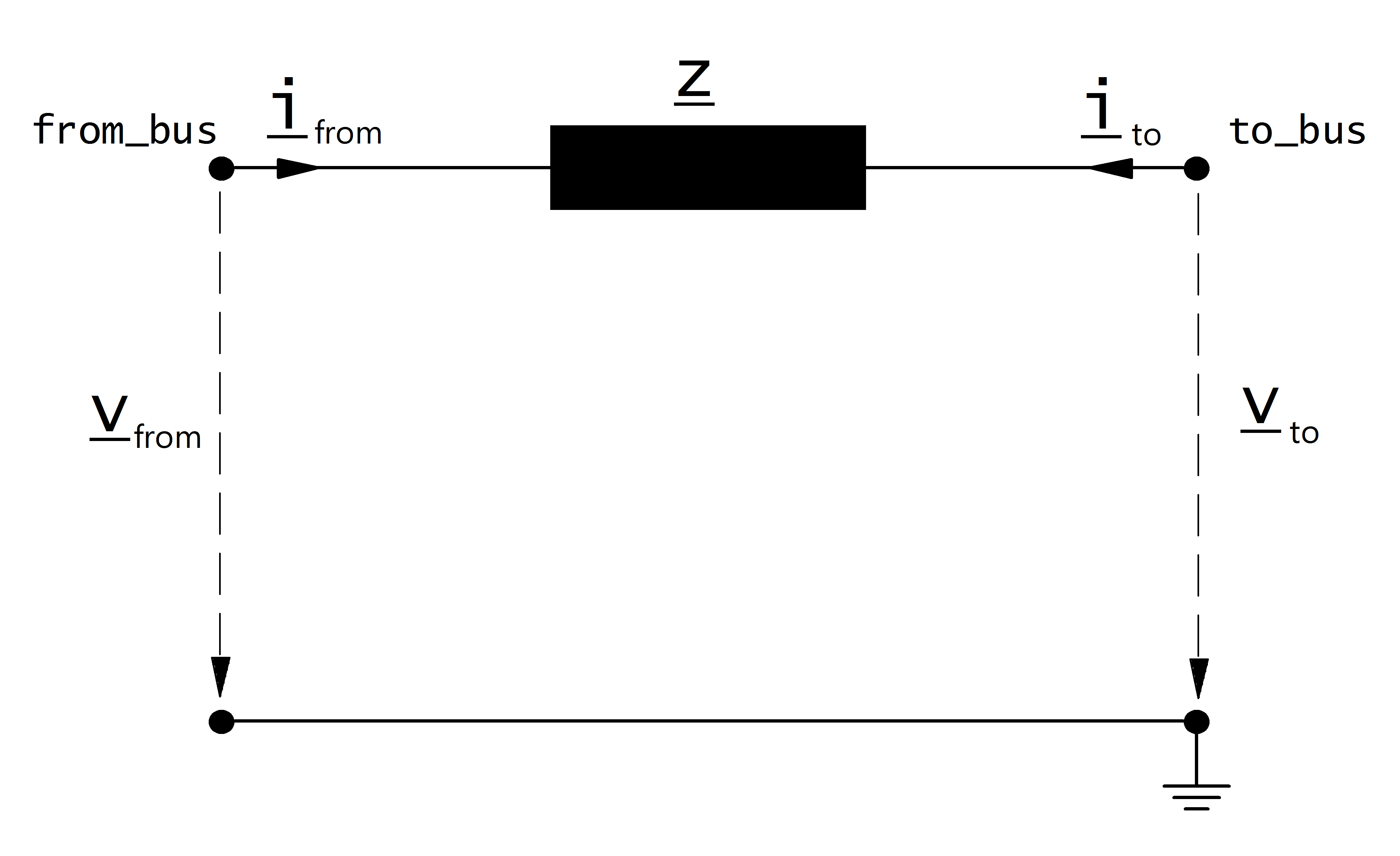
The per unit values given in the parameter table are assumed to be relative to the rated voltage of from and to bus as well as to the apparent power given in the table. The per unit values are therefore transformed into the network per unit system:
where \(S_{N}\) is the reference power of the per unit system (see Unit Systems and Conventions).
The asymmetric impedance results in an asymmetric nodal point admittance matrix:
Optionally, the impedance element can also have conductance and susceptance at the “from” and “to” buses. In this case, the electric model becomes similar to the line model. It is possible to have different values of susceptance and conductance for the “from” and “to” bus, as is in the case of the resistance and reactance. This provides for flexibility in modeling an impedance branch element, which will be especially useful when modeling grid equivalents.
Result Parameters
net.res_impedance
Parameter |
Datatype |
Explanation |
p_from_mw |
float |
active power flow into the impedance at “from” bus [MW] |
q_from_mvar |
float |
reactive power flow into the impedance at “from” bus [MVAr] |
p_to_mw |
float |
active power flow into the impedance at “to” bus [MW] |
q_to_mvar |
float |
reactive power flow into the impedance at “to” bus [MVAr] |
pl_mw |
float |
active power losses of the impedance [MW] |
ql_mvar |
float |
reactive power consumption of the impedance [MVar] |
i_from_ka |
float |
current at from bus [kA] |
i_to_ka |
float |
current at to bus [kA] |