Asymmetric Load
Note
Loads should always have a positive p_mw value, since all power values are given in the consumer system. If you want to model constant generation, use a Static Generator (asymmetric_sgen element) instead of a negative load.
See also
Create Function
- pandapower.create.create_asymmetric_load(net, bus, p_a_mw=0, p_b_mw=0, p_c_mw=0, q_a_mvar=0, q_b_mvar=0, q_c_mvar=0, sn_a_mva=nan, sn_b_mva=nan, sn_c_mva=nan, sn_mva=nan, name=None, scaling=1.0, index=None, in_service=True, type='wye', **kwargs)
Adds one 3 phase load in table net[“asymmetric_load”].
All loads are modelled in the consumer system, meaning load is positive and generation is negative active power. Please pay attention to the correct signing of the reactive power as well.
- Parameters:
net (pandapowerNet) – The net within this load should be created
bus (int | integer) – The bus id to which the load is connected
p_a_mw (float) – The active power for Phase A load
p_b_mw (float) – The active power for Phase B load
p_c_mw (float) – The active power for Phase C load
q_a_mvar (float) – The reactive power for Phase A load
q_b_mvar (float) – The reactive power for Phase B load
q_c_mvar (float) – The reactive power for Phase C load
sn_a_mva (float) – Nominal power for Phase A load
sn_b_mva (float) – Nominal power for Phase B load
sn_c_mva (float) – Nominal power for Phase C load
sn_mva (float) – Nominal power of the load
name (str | None) – The name for this load
scaling (float) – An OPTIONAL custom scaling factor. Multiplies with p_mw and q_mvar of all phases.
type (Literal['wye', 'delta']) – type variable to classify three ph load: delta/wye
index (int | integer | None) – Force a specified ID if it is available. If None, the index one higher than the highest already existing index is selected.
in_service (bool) – True for in_service or False for out of service
- Returns:
The ID of the created asymmetric load
- Return type:
int | integer
Example
>>> create_asymmetric_load(net, bus=0, p_c_mw=9., q_c_mvar=1.8)
Input Parameters
net.asymmetric_load
Parameter |
Datatype |
Value Range |
Explanation |
name |
string |
name of the load |
|
bus * |
integer |
index of connected bus |
|
p_a_mw* |
float |
\(\geq 0\) |
Phase A active power of the load [MW] |
p_b_mw* |
float |
\(\geq 0\) |
Phase B active power of the load [MW] |
p_c_mw* |
float |
\(\geq 0\) |
Phase C active power of the load [MW] |
q_a_mvar* |
float |
Phase A reactive power of the load [MVar] |
|
q_b_mvar* |
float |
Phase B reactive power of the load [MVar] |
|
q_c_mvar* |
float |
Phase C reactive power of the load [MVar] |
|
sn_mva |
float |
\(>0\) |
rated power of the load [MVA] |
scaling * |
float |
\(\geq 0\) |
scaling factor for active and reactive power |
in_service* |
boolean |
True / False |
specifies if the load is in service. |
type* |
String |
wye/delta |
Connection Type of 3 Phase Load (wye/delta connected) |
*necessary for executing a power flow calculation.
Note
The apparent power value sn_mva is provided as additional information for usage in controller or other applications based on pandapower. It is not considered in the power flow!
‘wye’ is the same as PH-E loads
For ‘delta’ loads line-earth voltages and powers are converted to line-line values
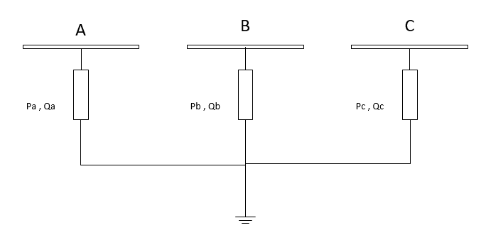
Electric Model
Loads are modelled as PQ-buses in the power flow calculation.
Wye Load
Delta Load
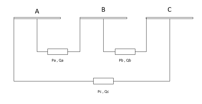
Even though power values are entered as Line-ground \(P_{a},Q_{a}\), for delta loads, Power values are actually line-line powers i.e. \(P_{ab},Q_{ab}\)
So, in the algorithm :
Line-ground voltages \(V_{a}\) are converted to line-line voltages \(V_{ab}\). Line-Line currents are then converted to Line-ground currents \(I_{a}\).
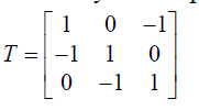
\(I_{a}= T. \frac{S_{ab}}{(V_{an}-V_{bn})}\)
\(I_{b}= T. \frac{S_{bc}}{(V_{bn}-V_{cn})}\)
\(I_{c}= T. \frac{S_{ca}}{(V_{cn}-V_{an})}\)
Where
Result Parameters
net.res_asymmetric_load
Parameter |
Datatype |
Explanation |
p_a_mw |
float |
resulting Phase A active power demand after scaling and after considering voltage dependence [MW] |
q_a_mvar |
float |
resulting Phase A reactive power demand after scaling and after considering voltage dependence [MVar] |
p_b_mw |
float |
resulting Phase B active power demand after scaling and after considering voltage dependence [MW] |
q_b_mvar |
float |
resulting Phase B reactive power demand after scaling and after considering voltage dependence [MVar] |
p_c_mw |
float |
resulting Phase C active power demand after scaling and after considering voltage dependence [MW] |
q_c_mvar |
float |
resulting Phase C reactive power demand after scaling and after considering voltage dependence [MVar] |