HV DC Link / DC Line
See also
Create Function
- pandapower.create_dcline(net, from_bus, to_bus, p_mw, loss_percent, loss_mw, vm_from_pu, vm_to_pu, index=None, name=None, max_p_mw=nan, min_q_from_mvar=nan, min_q_to_mvar=nan, max_q_from_mvar=nan, max_q_to_mvar=nan, in_service=True, **kwargs)
Creates a dc line.
- Parameters:
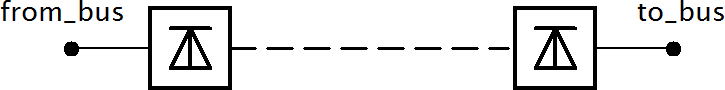
from_bus (int | integer) – ID of the bus on one side which the line will be connected with
to_bus (int | integer) – ID of the bus on the other side which the line will be connected with
p_mw (float) – Active power transmitted from ‘from_bus’ to ‘to_bus’
loss_percent (float) – Relative transmission loss in percent of active power transmission
loss_mw (float) – Total transmission loss in MW
vm_from_pu (float) – Voltage set point at from bus
vm_to_pu (float) – Voltage set point at to bus
index (int | integer | None) – Force a specified ID if it is available. If None, the index one higher than the highest already existing index is selected.
name (str | None) – A custom name for this dc line
in_service (bool) – True for in_service or False for out of service
max_p_mw (float) – Maximum active power flow. Only respected for OPF
min_q_from_mvar (float) – Minimum reactive power at from bus. Necessary for OPF
min_q_to_mvar (float) – Minimum reactive power at to bus. Necessary for OPF
max_q_from_mvar (float) – Maximum reactive power at from bus. Necessary for OPF
max_q_to_mvar (float) – Maximum reactive power at to bus. Necessary for OPF
net (pandapowerNet)
- Returns:
ID of the created element
- Return type:
int | integer
Example
>>> create_dcline(
>>>     net, from_bus=0, to_bus=1, p_mw=1e4, loss_percent=1.2, loss_mw=25, vm_from_pu=1.01, vm_to_pu=1.02
>>> )
Input Parameters
net.dcline
Parameter |
Datatype |
Value Range |
Explanation |
name |
string |
name of the generator |
|
from_bus* |
integer |
Index of bus where the dc line starts |
|
to_bus* |
integer |
Index of bus where the dc line ends |
|
p_mw* |
float |
Active power transmitted from ‘from_bus’ to ‘to_bus’ |
|
loss_percent* |
float |
\(>\) 0 |
Relative transmission loss in percent of active power transmission |
loss_mw* |
float |
\(>\) 0 |
Total transmission loss in MW |
vm_from_pu* |
float |
\(>\) 0 |
Voltage setpoint at from bus |
vm_to_pu* |
float |
\(>\) 0 |
Voltage setpoint at to bus |
max_p_mw** |
float |
\(>\) 0 |
Maximum active power transmission |
min_q_from_mvar** |
float |
Minimum reactive power at from bus |
|
max_q_from_mvar** |
float |
Maximum reactive power at from bus |
|
min_q_to_mvar** |
float |
Minimum reactive power at to bus |
|
max_q_to_mvar** |
float |
Maximum reactive power at to bus |
|
in_service* |
bool |
True/False |
specifies if DC line is in service |
*necessary for executing a power flow calculation
**optimal power flow parameter
Note
DC line is only able to model one-directional loadflow for now, which is why p_mw / max_p_mw have to be > 0.
Electric Model
A DC line is modelled as two generators in the loadflow:
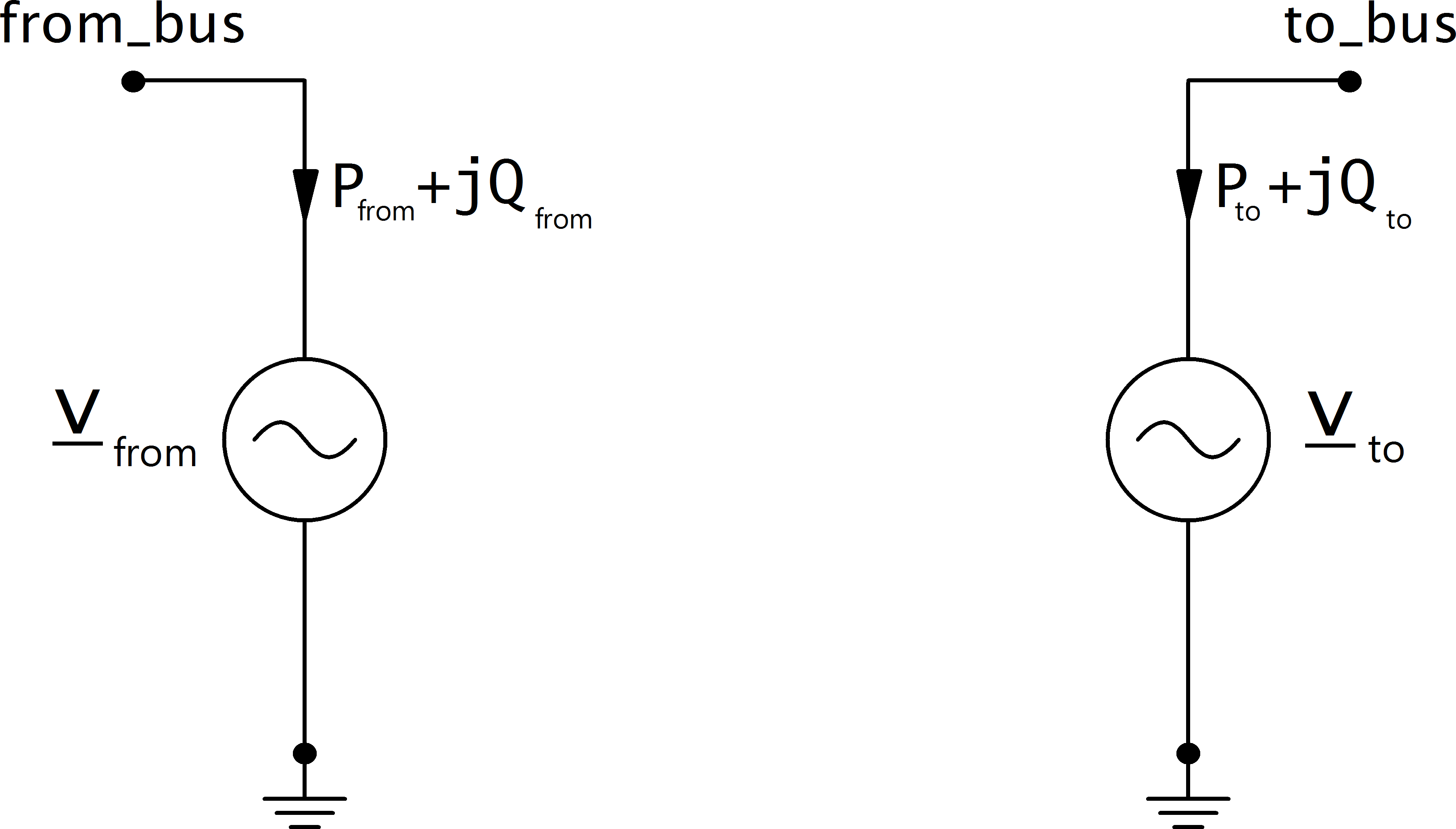
The active power at the from side is defined by the parameters in the dcline table. The active power at the to side is equal to the active power on the from side minus the losses of the DC line. If the active power is negative, the values are swapped: Meaning the current is flowing backwards from to_bus to from_bus. Also the active power limits are inverted, not the reactive power limits.
The voltage control with reactive power works just as described for the generator model. Maximum and Minimum reactive power limits are considered in the OPF, and in the PF if it is run with enforce_q_lims=True.
Result Parameters
net.res_dcline
Parameter |
Datatype |
Explanation |
p_from_mw |
float |
active power flow into the line at ‘from_bus’ [MW] |
q_from_mvar |
float |
reactive power flow into the line at ‘from_bus’ [kVar] |
p_to_mw |
float |
active power flow into the line at ‘to_bus’ [MW] |
q_to_mvar |
float |
reactive power flow into the line at ‘to_bus’ [kVar] |
pl_mw |
float |
active power losses of the line [MW] |
vm_from_pu |
float |
voltage magnitude at ‘from_bus’ [p.u] |
va_from_degree |
float |
voltage angle at ‘from_bus’ [degree] |
vm_to_pu |
float |
voltage magnitude at ‘to_bus’ [p.u] |
va_to_degree |
float |
voltage angle at ‘to_bus’ [degree] |