Transformer
Create Function
Transformers can be either created from the standard type library (create_transformer) or with custom values (create_transformer_from_parameters).
- pandapower.create.create_transformer(net, hv_bus, lv_bus, std_type, name=None, tap_pos=nan, in_service=True, index=None, max_loading_percent=nan, parallel=1, df=1.0, tap_changer_type=None, tap_dependency_table=False, id_characteristic_table=None, pt_percent=nan, oltc=False, xn_ohm=nan, rn_ohm=nan, tap2_pos=nan, **kwargs)
Creates a two-winding transformer in table net.trafo. The trafo parameters are defined through the standard type library.
- Parameters:
net (pandapowerNet) – the net within this transformer should be created
hv_bus (int | integer) – the bus on the high-voltage side on which the transformer will be connected to
lv_bus (int | integer) – the bus on the low-voltage side on which the transformer will be connected to
std_type (str) –
the used standard type from the standard type library
Zero sequence parameters (added through std_type for three-phase load flow):
vk0_percent (float): zero sequence relative short-circuit voltage
vkr0_percent (float): real part of zero sequence relative short-circuit voltage
- mag0_percent (float): ratio between magnetizing and short circuit impedance (zero sequence) as a percent
(z_mag0 / z0) * 100 %
mag0_rx (float): zero sequence magnetizing r/x ratio
si0_hv_partial (float): zero sequence short circuit impedance distribution in hv side
name (str | None) – a custom name for this transformer
tap_pos (int | float) – current tap position of the transformer. Defaults to the medium position (tap_neutral)
in_service (bool) – True for in_service or False for out of service
index (int | integer | None) – force a specified ID if it is available. If None, the index one higher than the highest already existing index is selected
max_loading_percent (float) – maximum current loading (only needed for OPF)
parallel (int) – number of parallel transformers
df (float) – derating factor: maximum current of transformer in relation to nominal current of transformer (from 0 to 1)
tap_dependency_table (bool) – True if transformer parameters (voltage ratio, angle, impedance) must be adjusted dependent on the tap position of the transformer. Requires the additional column “id_characteristic_table”. The function pandapower.control.trafo_characteristic_table_diagnostic can be used for sanity checks. The function pandapower.control.create_trafo_characteristic_object can be used to create SplineCharacteristic objects in the net.trafo_characteristic_spline table and add the additional column “id_characteristic_spline” to set up the reference to the spline characteristics.
id_characteristic_table (int | None) – references the index of the characteristic from the lookup table net.trafo_characteristic_table
tap_changer_type (str | None) – specifies the phase shifter type (“Ratio”, “Symmetrical”, “Ideal”, “Tabular”, None: no tap changer)
xn_ohm (float) – reactance of the neutral earthing impedance (Z_N) for short circuit calculation
rn_ohm (float) – resistance of the neutral earthing impedance (Z_N, e.g. a neutral earthing resistor) for short circuit calculation
tap2_pos (int | float) – current tap position of the second tap changer of the transformer. Defaults to the medium position (tap2_neutral)
pt_percent (float)
oltc (bool)
- Returns:
The ID of the created transformer
- Return type:
int | integer
Example
>>> create_transformer(net, hv_bus=0, lv_bus=1, std_type="0.4 MVA 10/0.4 kV", name="trafo1")
- pandapower.create.create_transformers(net, hv_buses, lv_buses, std_type, name=None, tap_pos=nan, in_service=True, index=None, max_loading_percent=nan, parallel=1, df=1.0, tap_changer_type=None, tap_dependency_table=False, id_characteristic_table=None, pt_percent=nan, oltc=False, xn_ohm=nan, rn_ohm=nan, tap2_pos=nan, **kwargs)
Creates several two-winding transformers in table net.trafo. Additional parameters passed will be added to the transformers dataframe. If keywords are passed that are present in the std_type they will override any setting from the standard type.
- Parameters:
net (pandapowerNet) – the pandapower network to which the transformers should be added
hv_buses (Sequence) – a Sequence of bus ids that are the high voltage buses for the transformers
lv_buses (Sequence) – a Sequence of bus ids that are the low valtage buses for the transformers
std_type (str) – the transformer std_type to get the not specified parameters from
name (Iterable[str] | None) – names for the transformers, default None
tap_pos (int | Iterable[int] | float) – current tap position of the transformers. Defaults to the medium position (tap_neutral), default nan
in_service (bool | Iterable[bool]) – Wheather the transforers are in or out of service, default True
index (int | integer | Iterable[int | integer] | None) – the index to use for the new elements, default None
max_loading_percent (float | Iterable[float]) – the maximum loading percentage of the transformer, default nan
parallel (int | Iterable[int]) – number of parallel transformer, default 1
df (float | Iterable[float]) – derating factor: maximum current of transformer in relation to nominal current of transformer (0 - 1), default 1.0
tap_changer_type (Literal['Ratio', 'Symmetrical', 'Ideal', 'Tabular'] | ~typing.Iterable[str] | None) – specifies the phase shifter type (“Ratio”, “Symmetrical”, “Ideal”, “Tabular” or None), default None
tap_dependency_table (bool | Iterable[bool]) – True if sanity checks should be performed. See SplineCharacteristics, default False
id_characteristic_table (int | Iterable[int] | None) – id of the SplineCharacteristic, default None
pt_percent (float | Iterable[float]) – default nan
oltc (bool | Iterable[bool]) – default False
xn_ohm (float | Iterable[float]) – reactance of the neutral earthing impedance (Z_N) for short circuit calculation, default nan
rn_ohm (float | Iterable[float]) – resistance of the neutral earthing impedance (Z_N, e.g. a neutral earthing resistor) for short circuit calculation, default nan
tap2_pos (int | Iterable[int] | float) – current tap position of the second tap changer ot the transformer. Defaults to the medium position (tap2_neutral), default nan
- Returns:
The IDs of the created transformers
- Return type:
ndarray[tuple[Any, …], dtype[int | integer]]
Example
>>> create_transformers(
>>>     net, hv_bus=[0, 1], lv_bus=[2, 3], std_type="0.4 MVA 10/0.4 kV", name=["trafo1", "trafo2"]
>>> )
- pandapower.create.create_transformer_from_parameters(net, hv_bus, lv_bus, sn_mva, vn_hv_kv, vn_lv_kv, vkr_percent, vk_percent, pfe_kw, i0_percent, shift_degree=0.0, tap_side=None, tap_neutral=nan, tap_max=nan, tap_min=nan, tap_step_percent=nan, tap_step_degree=nan, tap_pos=nan, tap_changer_type=None, id_characteristic_table=None, in_service=True, name=None, vector_group=None, index=None, max_loading_percent=nan, parallel=1, df=1.0, vk0_percent=nan, vkr0_percent=nan, mag0_percent=nan, mag0_rx=nan, si0_hv_partial=nan, pt_percent=nan, oltc=False, tap_dependency_table=False, xn_ohm=nan, rn_ohm=nan, tap2_side=None, tap2_neutral=nan, tap2_max=nan, tap2_min=nan, tap2_step_percent=nan, tap2_step_degree=nan, tap2_pos=nan, tap2_changer_type=None, **kwargs)
Creates a two-winding transformer in table net.trafo with the specified parameters.
- Parameters:
net (pandapowerNet) – the net within this transformer should be created
hv_bus (int | integer) – the bus on the high-voltage side on which the transformer will be connected to
lv_bus (int | integer) – the bus on the low-voltage side on which the transformer will be connected to
sn_mva (float) – rated apparent power
vn_hv_kv (float) – rated voltage on high voltage side
vn_lv_kv (float) – rated voltage on low voltage side
vkr_percent (float) – real part of relative short-circuit voltage
vk_percent (float) – relative short-circuit voltage
pfe_kw (float) – iron losses in kW
i0_percent (float) – open loop losses in percent of rated current
vector_group (str | None) – vector group of the transformer HV side is Uppercase letters and LV side is lower case
vk0_percent (float) – zero sequence relative short-circuit voltage
vkr0_percent (float) – real part of zero sequence relative short-circuit voltage
mag0_percent (float) – ratio between magnetizing and short circuit impedance (zero sequence) as a percent (z_mag0 / z0) * 100 %
mag0_rx (float) – zero sequence magnetizing R/X ratio
si0_hv_partial (float) – Distribution of zero sequence leakage impedance’s for HV side
in_service (bool) – True for in_service or False for out of service
parallel (int) – number of parallel transformers
name (str | None) – A custom name for this transformer
shift_degree (float) – angle shift over the transformer*
tap_side (Literal['hv', 'lv'] | None) – position of tap changer (“hv”, “lv”)
tap_pos (int | float) – current tap position of the transformer. Defaults to the medium position (tap_neutral)
tap_neutral (int | float) – tap position where the transformer ratio is equal to the ratio of the rated voltages
tap_max (int | float) – maximum allowed tap position
tap_min (int | float) – minimum allowed tap position
tap_step_percent (float) – tap step size for voltage magnitude in percent
tap_step_degree (float) – tap step size for voltage angle in degree*
tap_changer_type (Literal['Ratio', 'Symmetrical', 'Ideal', 'Tabular'] | None) – specifies the phase shifter type (“Ratio”, “Symmetrical”, “Ideal”, “Tabular”, None: no tap changer)*
index (int | integer | None) – force a specified ID if it is available. If None, the index one higher than the highest already existing index is selected.
max_loading_percent (float) – maximum current loading (only needed for OPF)
df (float) – derating factor - maximum current of transformer in relation to nominal current of transformer (from 0 to 1)
tap_dependency_table (bool) – True if transformer parameters (voltage ratio, angle, impedance) must be adjusted dependent on the tap position of the transformer. Requires the additional column “id_characteristic_table”. The function pandapower.control.trafo_characteristic_table_diagnostic can be used for sanity checks. The function pandapower.control.create_trafo_characteristic_object can be used to create SplineCharacteristic objects in the net.trafo_characteristic_spline table and add the additional column “id_characteristic_spline” to set up the reference to the spline characteristics.
id_characteristic_table (int | None) – references the index of the characteristic from the lookup table net.trafo_characteristic_table
pt_percent (float) – (short circuit only)
oltc (bool) – (short circuit only)
xn_ohm (float) – reactance of the neutral earthing impedance (Z_N) for short circuit calculation
rn_ohm (float) – resistance of the neutral earthing impedance (Z_N, e.g. a neutral earthing resistor) for short circuit calculation
tap2_side (Literal['hv', 'lv'] | None) – position of the second tap changer (“hv”, “lv”)
tap2_pos (int | float) – current tap position of the second tap changer of the transformer. Defaults to the medium position (tap2_neutral)
tap2_neutral (int | float) – second tap position where the transformer ratio is equal to the ratio of the rated voltages
tap2_max (int | float) – maximum allowed tap position of the second tap changer
tap2_min (int | float) – minimum allowed tap position of the second tap changer
tap2_step_percent (float) – second tap step size for voltage magnitude in percent
tap2_step_degree (float) – second tap step size for voltage angle in degree*
tap2_changer_type (Literal['Ratio', 'Symmetrical', 'Ideal'] | None) –
specifies the tap changer type (“Ratio”, “Symmetrical”, “Ideal”, None: no tap changer)*
* only considered in load flow if calculate_voltage_angles = True
- Keyword Arguments:
leakage_resistance_ratio_hv – ratio of transformer short-circuit resistance on HV side (default 0.5)
leakage_reactance_ratio_hv – ratio of transformer short-circuit reactance on HV side (default 0.5)
- Returns:
index (int) - the unique ID of the created transformer
- Return type:
int | integer
Example
>>> create_transformer_from_parameters(
>>>     net, hv_bus=0, lv_bus=1, name="trafo1", sn_mva=40, vn_hv_kv=110, vn_lv_kv=10, vk_percent=10,
>>>     vkr_percent=0.3, pfe_kw=30, i0_percent=0.1, shift_degree=30
>>> )
- pandapower.create.create_transformers_from_parameters(net, hv_buses, lv_buses, sn_mva, vn_hv_kv, vn_lv_kv, vkr_percent, vk_percent, pfe_kw, i0_percent, shift_degree=0.0, tap_side=None, tap_neutral=nan, tap_max=nan, tap_min=nan, tap_step_percent=nan, tap_step_degree=nan, tap_pos=nan, tap_changer_type=None, id_characteristic_table=None, in_service=True, name=None, vector_group=None, index=None, max_loading_percent=nan, parallel=1, df=1.0, vk0_percent=nan, vkr0_percent=nan, mag0_percent=nan, mag0_rx=nan, si0_hv_partial=nan, pt_percent=nan, oltc=False, tap_dependency_table=False, xn_ohm=nan, rn_ohm=nan, tap2_side=None, tap2_neutral=nan, tap2_max=nan, tap2_min=nan, tap2_step_percent=nan, tap2_step_degree=nan, tap2_pos=nan, tap2_changer_type=None, **kwargs)
Creates several two-winding transformers in table net.trafo with the specified parameters.
- Parameters:
net (pandapowerNet) – the net within this transformer should be created
hv_buses (Sequence) – the bus on the high-voltage side on which the transformer will be connected to
lv_buses (Sequence) – the bus on the low-voltage side on which the transformer will be connected to
sn_mva (float | Iterable[float]) – rated apparent power
vn_hv_kv (float | Iterable[float]) – rated voltage on high voltage side
vn_lv_kv (float | Iterable[float]) – rated voltage on low voltage side
vkr_percent (float | Iterable[float]) – real part of relative short-circuit voltage
vk_percent (float | Iterable[float]) – relative short-circuit voltage
pfe_kw (float | Iterable[float]) – iron losses in kW
i0_percent (float | Iterable[float]) – open loop losses in percent of rated current
vector_group (str | Iterable[str] | None) – Vector group of the transformer HV side is Uppercase letters and LV side is lower case
vk0_percent (float | Iterable[float]) – zero sequence relative short-circuit voltage
vkr0_percent (float | Iterable[float]) – real part of zero sequence relative short-circuit voltage
mag0_percent (float | Iterable[float]) – ratio between magnetizing and short circuit impedance (zero sequence) as a percent (z_mag0 / z0) * 100 %
mag0_rx (float | Iterable[float]) – zero sequence magnetizing R/X ratio
si0_hv_partial (float | Iterable[float]) – distribution of zero sequence leakage impedance’s for HV side
in_service (bool | Iterable[bool]) – True for in_service or False for out of service
parallel (int | Iterable[int]) – number of parallel transformers
name (Iterable[str] | None) – a custom name for this transformer
shift_degree (float | Iterable[float]) – angle shift over the transformer*
tap_side (Literal['hv', 'lv'] | ~typing.Iterable[str] | None) – position of tap changer (“hv”, “lv”)
tap_pos (int | Iterable[int] | float) – current tap position of the transformer. Defaults to the neutral tap position (tap_neutral)
tap_neutral (int | Iterable[int] | float) – tap position where the transformer ratio is equal to the ratio of the rated voltages
tap_max (int | Iterable[int] | float) – maximum allowed tap position
tap_min (int | Iterable[int] | float) – minimum allowed tap position
tap_step_percent (float | Iterable[float]) – tap step size for voltage magnitude in percent
tap_step_degree (float | Iterable[float]) – tap step size for voltage angle in degree*
tap_changer_type (Literal['Ratio', 'Symmetrical', 'Ideal', 'Tabular'] | ~typing.Iterable[str] | None) – specifies the tap changer type (“Ratio”, “Symmetrical”, “Ideal”, “Tabular”, None: no tap changer)*
index (int | integer | Iterable[int | integer] | None) – force a specified ID if it is available. If None, the index one higher than the highest already existing index is selected.
max_loading_percent (float | Iterable[float]) – maximum current loading (only needed for OPF)
df (float | Iterable[float]) – derating factor - maximum current of transformer in relation to nominal current of transformer (from 0 to 1)
tap_dependency_table (bool | Iterable[bool]) – True if transformer parameters (voltage ratio, angle, impedance) must be adjusted dependent on the tap position of the transformer. Requires the additional column “id_characteristic_table”. The function pandapower.control.trafo_characteristic_table_diagnostic can be used for sanity checks. The function pandapower.control.create_trafo_characteristic_object can be used to create SplineCharacteristic objects in the net.trafo_characteristic_spline table and add the additional column “id_characteristic_spline” to set up the reference to the spline characteristics.
id_characteristic_table (int | Iterable[int] | None) – references the index of the characteristic from the lookup table net.trafo_characteristic_table
pt_percent (float | Iterable[float]) – (short circuit only)
oltc (bool | Iterable[bool]) – (short circuit only)
xn_ohm (float | Iterable[float]) – reactance of the neutral earthing impedance (Z_N) for short circuit calculation
rn_ohm (float | Iterable[float]) – resistance of the neutral earthing impedance (Z_N, e.g. a neutral earthing resistor) for short circuit calculation
tap2_side (Literal['hv', 'lv'] | ~typing.Iterable[str] | None) – position of the second tap changer (“hv”, “lv”)
tap2_pos (int | Iterable[int] | float) – current tap position of the second tap changer of the transformer. Defaults to the medium position (tap2_neutral)
tap2_neutral (int | Iterable[int] | float) – second tap position where the transformer ratio is equal to the ratio of the rated voltages
tap2_max (int | Iterable[int] | float) – maximum allowed tap position of the second tap changer
tap2_min (int | Iterable[int] | float) – minimum allowed tap position of the second tap changer
tap2_step_percent (float | Iterable[float]) – second tap step size for voltage magnitude in percent
tap2_step_degree (float | Iterable[float]) – second tap step size for voltage angle in degree*
tap2_changer_type (Literal['Ratio', 'Symmetrical', 'Ideal'] | ~typing.Iterable[str] | None) –
specifies the tap changer type (“Ratio”, “Symmetrical”, “Ideal”, None: no tap changer)*
* only considered in load flow if calculate_voltage_angles = True
- Returns:
The list of IDs of the created transformers
- Return type:
ndarray[tuple[Any, …], dtype[int | integer]]
Example
>>> create_transformers_from_parameters(
>>>     net, hv_bus=[0, 1], lv_bus=[2, 3], name="trafo1", sn_mva=40, vn_hv_kv=110, vn_lv_kv=10, vk_percent=10,
>>>     vkr_percent=0.3, pfe_kw=30, i0_percent=0.1, shift_degree=30
>>> )
Input Parameters
net.trafo
Parameter |
Datatype |
Value Range |
Explanation |
name |
string |
name of the transformer |
|
std_type |
string |
transformer standard type name |
|
hv_bus* |
integer |
high voltage bus index of the transformer |
|
lv_bus* |
integer |
low voltage bus index of the transformer |
|
sn_mva* |
float |
\(>\) 0 |
rated apparent power of the transformer [MVA] |
vn_hv_kv* |
float |
\(>\) 0 |
rated voltage at high voltage bus [kV] |
vn_lv_kv* |
float |
\(>\) 0 |
rated voltage at low voltage bus [kV] |
vk_percent* |
float |
\(>\) 0 |
short circuit voltage [%] |
vkr_percent* |
float |
\(\geq\) 0 |
real component of short circuit voltage [%] |
pfe_kw* |
float |
\(\geq\) 0 |
iron losses [kW] |
i0_percent* |
float |
\(\geq\) 0 |
open loop losses in [%] |
vk0_percent*** |
float |
\(\geq\) 0 |
zero sequence relative short-circuit voltage |
vkr0_percent*** |
float |
\(\geq\) 0 |
real part of zero sequence relative short-circuit voltage |
mag0_percent*** |
float |
\(\geq\) 0 |
z_mag0 / z0 ratio between magnetizing and short circuit impedance (zero sequence) as a percent |
mag0_rx*** |
float |
zero sequence magnetizing r/x ratio |
|
si0_hv_partial*** |
float |
\(\geq\) 0 |
zero sequence short circuit impedance distribution in hv side |
vector_group*** |
String |
‘Dyn’,’Yyn’,’Yzn’,’YNyn’ |
Vector Groups ( required for zero sequence model of transformer ) |
shift_degree* |
float |
transformer phase shift angle |
|
tap_side |
string |
“hv”, “lv” |
defines if tap changer is at the high- or low voltage side |
tap_neutral |
integer |
rated tap position |
|
tap_min |
integer |
minimum tap position |
|
tap_max |
integer |
maximum tap position |
|
tap_step_percent |
float |
\(>\) 0 |
tap step size for voltage magnitude [%] |
tap_step_degree |
float |
\(\geq\) 0 |
tap step size for voltage angle |
tap_pos |
integer |
current position of tap changer |
|
tap_changer_type |
string |
“Ratio”, “Symmetrical”, “Ideal”, “Tabular” |
specifies the tap changer type |
tap_dependency_table |
boolean |
True / False |
whether the transformer parameters (voltage ratio, angle, impedance) are adjusted dependent on the tap position of the transformer |
id_characteristic_table |
integer |
\(\geq\) 0 |
references the id_characteristic index from the trafo_characteristic_table |
parallel |
integer |
\(>\) 0 |
number of parallel transformers |
max_loading_percent** |
float |
\(>\) 0 |
Maximum loading of the transformer with respect to sn_mva and its corresponding current at 1.0 p.u. |
df |
float |
1 \(\geq\) df \(>\) 0 |
derating factor: maximum current of transformer in relation to nominal current of transformer (from 0 to 1) |
in_service* |
boolean |
True / False |
specifies if the transformer is in service |
oltc* |
boolean |
True / False |
specifies if the transformer has an OLTC (short-circuit relevant) |
power_station_unit* |
boolean |
True / False |
specifies if the transformer is part of a power_station_unit (short-circuit relevant) |
tap2_side**** |
string |
“hv”, “lv” |
defines if tap changer is at the high- or low voltage side |
tap2_neutral**** |
integer |
rated tap position |
|
tap2_min**** |
integer |
minimum tap position |
|
tap2_max**** |
integer |
maximum tap position |
|
tap2_step_percent**** |
float |
\(>\) 0 |
tap step size for voltage magnitude [%] |
tap2_step_degree**** |
float |
\(\geq\) 0 |
tap step size for voltage angle |
tap2_pos**** |
integer |
current position of tap changer |
|
tap2_changer_type**** |
string |
“Ratio”, “Symmetrical”, “Ideal” |
specifies the tap changer type |
leakage_resistance_ratio_hv* |
float |
0 \(\leq\) 1 |
ratio of transformer short-circuit resistance on HV side (default 0.5) |
leakage_reactance_ratio_hv* |
float |
0 \(\leq\) 1 |
ratio of transformer short-circuit reactance on HV side (default 0.5) |
*necessary for executing a balanced power flow calculation
**optimal power flow parameter
***necessary for executing a three phase power flow / single phase short circuit
****optional, for modeling a second tap changer
Note
The transformer loading constraint for the optimal power flow corresponds to the option trafo_loading=”current”:
Note
vkr_percent can be calculated as follow :
Electric Model
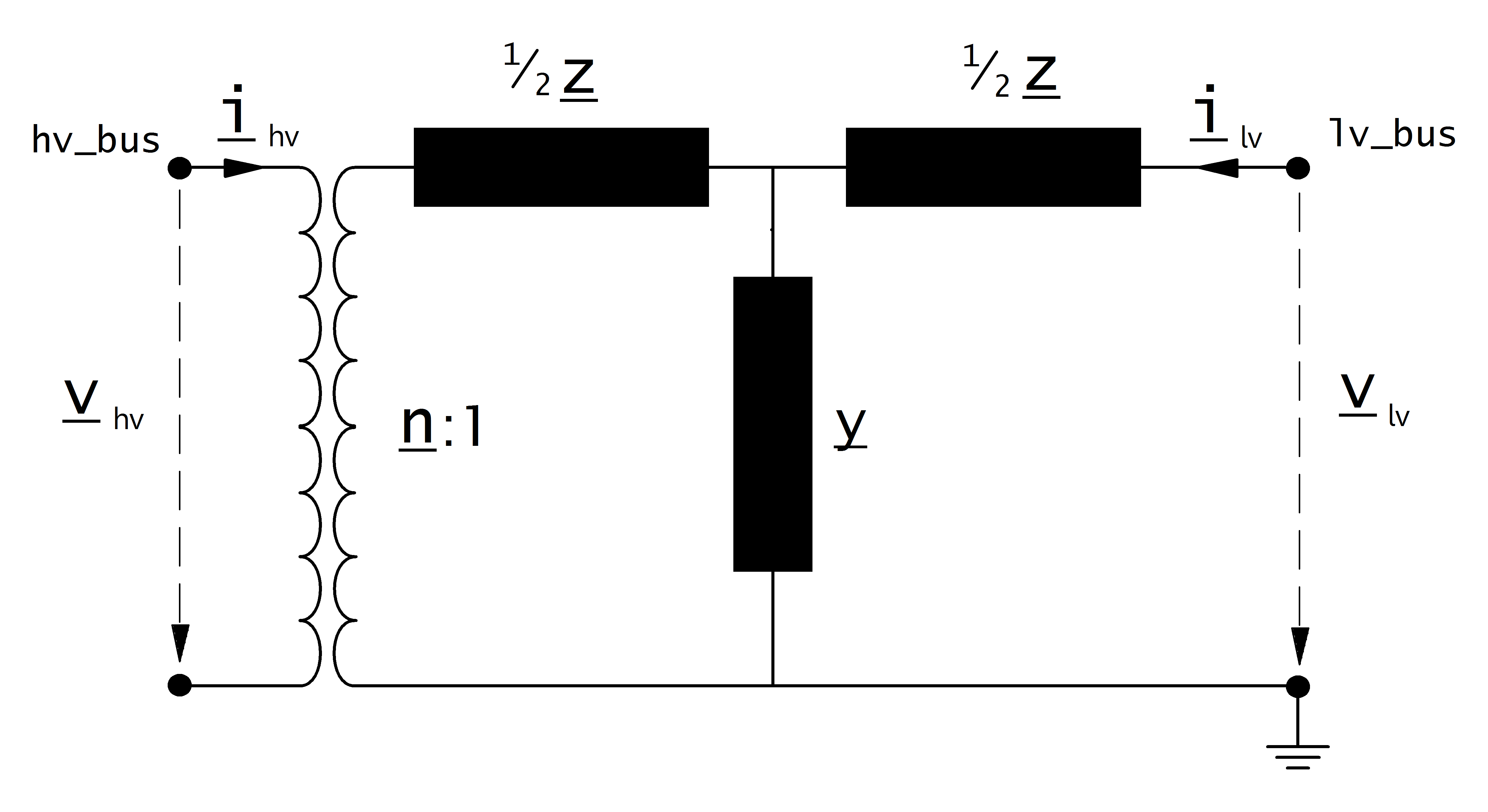
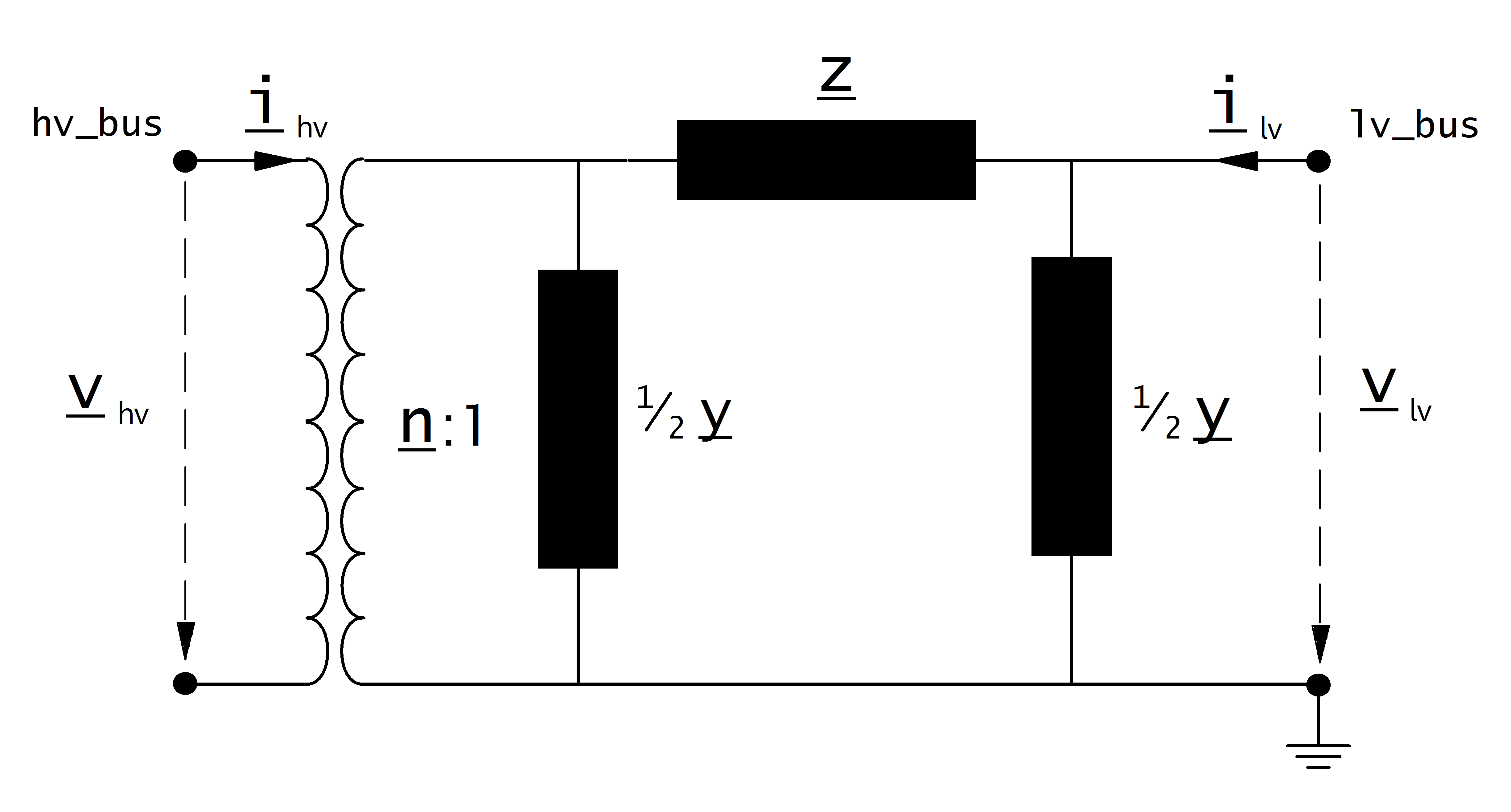
The equivalent circuit used for the transformer can be set in the power flow with the parameter “trafo_model”.
trafo_model=’t’:
sequence = 0:
trafo_model=’pi’:
Note
it is possible to specify unequal distributions of leakage resistance and reactance between HV and LV sides
Transformer Ratio
The magnitude of the transformer ratio is given as:
The reference voltages of the high and low voltage buses are taken from the net.bus table. The reference voltage of the transformer is taken directly from the transformer table:
If the power flow is run with voltage_angles=True, the complex ratio is given as:
Otherwise, the ratio does not include a phase shift:
Impedance Values
The short-circuit impedance is calculated as:
The magnetising admittance is calculated as:
The values calculated in that way are relative to the rated values of the transformer. To transform them into the per unit system, they have to be converted to the rated values of the network:
Where the reference voltage \(V_{N}\) is the nominal voltage at the low voltage side of the transformer and the rated apparent power \(S_{N}\) is defined system wide in the net object (see Unit Systems and Conventions).
Tap Changer
Longitudinal regulator (Ratio Tap Changer)
A longitudinal regulator can be modeled by setting tap_changer_type to “Ratio” and defining the tap changer voltage step with tap_step_percent.
The reference voltage is then multiplied with the tap factor:
On which side the reference voltage is adapted depends on the \(tap\_side\) variable:
tap_side=”hv” |
tap_side=”lv” |
|
\(V_{n, HV, transformer}\) |
\(vnh\_kv \cdot n_{tap}\) |
\(vnh\_kv\) |
\(V_{n, LV, transformer}\) |
\(vnl\_kv\) |
\(vnl\_kv \cdot n_{tap}\) |
Note
The variables tap_min and tap_max are not considered in the power flow. The user is responsible to ensure that tap_min < tap_pos < tap_max!
Cross regulator (Ratio Tap Changer / Symmetrical Tap Changer)
In addition to tap_step_percent, the tap_step_degree parameter can be populated to model the fixed angle between the vectors of the input voltage and additional voltage per tap step \(\delta U\) (not tap-dependent). This results in a cross regulator that affects the magnitude as well as the angle of the output voltage. Use tap_changer_type “Ratio”, or if the fixed angle \(\theta\) is 90 degrees, set tap_step_degree to 90 and use tap_changer_type “Symmetrical”.
Ideal phase shifter
If tap_changer_type is set to “Ideal”, the tap changer is modeled as an ideal phase shifter, meaning that a constant angle shift is added with each tap step:
The angle shift can be directly defined in tap_step_degree (the same parameter as for “Ratio” tap changer is used!), in which case:
or it can be given as a constant voltage step in tap_step_percent, in which case the angle is calculated as:
If both values are given for an ideal phase shift transformer, the power flow will raise an error.
Tabular phase shifter
If tap_changer_type is set to “Tabular”, the transformer ratio and phase angle shift per tap step is defined in the trafo_characteristic_table (see below). One application of the “Tabular” tap changer type is to represent the PhaseTapChangerTabular class defined in the CIM CGMES dataset. In this case, tap_dependency_table flag must be set to True.
Trafo characteristic table
A transformer characteristic table (trafo_characteristic_table) can be used to adjust the transformer parameters (voltage ratio, angle, impedance (Note: Zero sequence components and adjust nominal power factor are also possible entries, but not yet implemented)) according to the selected tap position. This lookup table is created automatically from version 3.0 onwards through the CIM CGMES to pandapower converter (if this information is available in the EQ profile), the powerfactory to pandapower converter, or the user may define this table manually. The id_characteristic_table variable in net.trafo references the id_characteristic column in net.trafo_characteristic_table per transformer.
If the tap_dependency_table variable in net.trafo is set to True, this indicates that there is a corresponding characteristic available in net.trafo_characteristic_table, which overwrites the default trafo parameters tap_step_percent, tap_step_degree, vk_percent and vkr_percent. If tap_dependency_table is set to True, tapat_star_point has no effect.
The below table provides an example trafo_characteristic_table, populated for two 2-winding transformers.
id_characteristic |
step |
voltage_ratio |
angle_deg |
vk_percent |
vkr_percent |
vkr_hv_percent |
vkr_mv_percent |
vkr_lv_percent |
vk_hv_percent |
vk_mv_percent |
vk_lv_percent |
|
0 |
0 |
1 |
1.056666613 |
0 |
16.5299996 |
0.209176484 |
||||||
1 |
0 |
2 |
1.037777782 |
0 |
16.43000257 |
0.210313729 |
||||||
2 |
0 |
3 |
1.018888831 |
0 |
16.32999957 |
0.211450973 |
||||||
3 |
0 |
4 |
1 |
0 |
16.23000167 |
0.212588267 |
||||||
4 |
0 |
5 |
0.99000001 |
0 |
16.22176222 |
0.216951523 |
||||||
5 |
0 |
6 |
0.980000019 |
0 |
16.21353032 |
0.221314877 |
||||||
6 |
0 |
7 |
0.970000029 |
0 |
16.20529492 |
0.225678207 |
||||||
7 |
1 |
-5 |
1.00160718 |
-3.246266842 |
19.4996906 |
0.181380227 |
||||||
8 |
1 |
-4 |
1.001028895 |
-2.598013878 |
19.27375038 |
0.17510416 |
||||||
9 |
1 |
-3 |
1.00057888 |
-1.949094653 |
19.04781394 |
0.168828137 |
||||||
10 |
1 |
-2 |
1.000257373 |
-1.299674988 |
18.82187847 |
0.162552115 |
||||||
11 |
1 |
-1 |
1.000064373 |
-0.649921119 |
18.5959397 |
0.15627607 |
||||||
12 |
1 |
0 |
1 |
0 |
18.37000339 |
0.150000025 |
||||||
13 |
1 |
1 |
1.000064373 |
0.649921119 |
17.93187445 |
0.146578107 |
||||||
14 |
1 |
2 |
1.000257373 |
1.299675107 |
17.49375268 |
0.143156245 |
||||||
15 |
1 |
3 |
1.00057888 |
1.949094653 |
17.05562518 |
0.139734361 |
||||||
16 |
1 |
4 |
1.001028895 |
2.598013878 |
16.61749911 |
0.1363125 |
||||||
17 |
1 |
5 |
1.00160718 |
3.246266842 |
16.17937448 |
0.132890616 |
Note
net.trafo_characteristic_table is applicable to both 2-winding and 3-winding transformers; the corresponding impedance parameters are populated accordingly.
tap_dependency_table has to be set to True, and id_characteristic_table and tap_changer_type variables need to be populated in order to consider the corresponding trafo_characteristic_table values.
Only one tap_dependency_table is supported per 2-winding transformer (there is no tap2_dependency_table variable).
The function pandapower.control.trafo_characteristic_table_diagnostic can be used for sanity checks. The function pandapower.control.create_trafo_characteristic_object can be used to automatically create SplineCharacteristic objects and populate the net.trafo_characteristic_spline table according to the net.trafo_characteristic_table table. An additional column id_characteristic_spline is also created in net.trafo to set up the reference to the spline characteristics.
The below table provides an example trafo_characteristic_spline table, populated for two 2-winding transformers.
id_characteristic |
voltage_ratio_characteristic |
angle_deg_characteristic |
vk_percent_characteristic |
vkr_percent_characteristic |
vk_hv_percent_characteristic |
vkr_hv_percent_characteristic |
vk_mv_percent_characteristic |
vkr_mv_percent_characteristic |
vk_lv_percent_characteristic |
vkr_lv_percent_characteristic |
|
0 |
0 |
SplineCharacteristic |
SplineCharacteristic |
SplineCharacteristic |
SplineCharacteristic |
||||||
1 |
1 |
SplineCharacteristic |
SplineCharacteristic |
SplineCharacteristic |
SplineCharacteristic |
Result Parameters
net.res_trafo
Parameter |
Datatype |
Explanation |
p_hv_mw |
float |
active power flow at the high voltage transformer bus [MW] |
q_hv_mvar |
float |
reactive power flow at the high voltage transformer bus [MVar] |
p_lv_mw |
float |
active power flow at the low voltage transformer bus [MW] |
q_lv_mvar |
float |
reactive power flow at the low voltage transformer bus [MVar] |
pl_mw |
float |
active power losses of the transformer [MW] |
ql_mvar |
float |
reactive power consumption of the transformer [Mvar] |
i_hv_ka |
float |
current at the high voltage side of the transformer [kA] |
i_lv_ka |
float |
current at the low voltage side of the transformer [kA] |
vm_hv_pu |
float |
voltage magnitude at the high voltage bus [pu] |
vm_lv_pu |
float |
voltage magnitude at the low voltage bus [pu] |
va_hv_degree |
float |
voltage angle at the high voltage bus [degrees] |
va_lv_degree |
float |
voltage angle at the low voltage bus [degrees] |
loading_percent |
float |
load utilization relative to rated power [%] |
net.res_trafo_3ph
Parameter |
Datatype |
Explanation |
p_a_hv_mw |
float |
active power flow at the high voltage transformer bus : Phase A [MW] |
q_a_hv_mvar |
float |
reactive power flow at the high voltage transformer bus : Phase A [MVar] |
p_b_hv_mw |
float |
active power flow at the high voltage transformer bus : Phase B [MW] |
q_b_hv_mvar |
float |
reactive power flow at the high voltage transformer bus : Phase B [MVar] |
p_c_hv_mw |
float |
active power flow at the high voltage transformer bus : Phase C [MW] |
q_c_hv_mvar |
float |
reactive power flow at the high voltage transformer bus : Phase C [MVar] |
p_a_lv_mw |
float |
active power flow at the low voltage transformer bus : Phase A [MW] |
q_a_lv_mvar |
float |
reactive power flow at the low voltage transformer bus : Phase A [MVar] |
p_b_lv_mw |
float |
active power flow at the low voltage transformer bus : Phase B [MW] |
q_b_lv_mvar |
float |
reactive power flow at the low voltage transformer bus : Phase B [MVar] |
p_c_lv_mw |
float |
active power flow at the low voltage transformer bus : Phase C [MW] |
q_c_lv_mvar |
float |
reactive power flow at the low voltage transformer bus : Phase C [MVar] |
pl_a_mw |
float |
active power losses of the transformer : Phase A [MW] |
ql_a_mvar |
float |
reactive power consumption of the transformer : Phase A [Mvar] |
pl_b_mw |
float |
active power losses of the transformer : Phase B [MW] |
ql_b_mvar |
float |
reactive power consumption of the transformer : Phase B [Mvar] |
pl_c_mw |
float |
active power losses of the transformer : Phase C [MW] |
ql_c_mvar |
float |
reactive power consumption of the transformer : Phase C [Mvar] |
i_a_hv_ka |
float |
current at the high voltage side of the transformer : Phase A [kA] |
i_a_lv_ka |
float |
current at the low voltage side of the transformer : Phase A [kA] |
i_b_hv_ka |
float |
current at the high voltage side of the transformer : Phase B [kA] |
i_b_lv_ka |
float |
current at the low voltage side of the transformer : Phase B [kA] |
i_c_hv_ka |
float |
current at the high voltage side of the transformer : Phase C [kA] |
i_c_lv_ka |
float |
current at the low voltage side of the transformer : Phase C [kA] |
loading_a_percent |
float |
load utilization relative to rated power: Phase A [%] |
loading_b_percent |
float |
load utilization relative to rated power: Phase B [%] |
loading_c_percent |
float |
load utilization relative to rated power: Phase C [%] |
loading_percent |
float |
load utilization relative to rated power: Maximum of Phase A, B, C in [%] |
The definition of the transformer loading depends on the trafo_loading parameter of the power flow.
For trafo_loading=”current”, the loading is calculated as:
For trafo_loading=”power”, the loading is defined as:
net.res_trafo_sc
The short-circuit (SC) results are put into net.res_trafo_sc with following definitions:
Parameter |
Datatype |
Explanation |
ikss_hv_ka |
float |
magnitude of the initial SC current at HV transformer bus [kA] |
ikss_hv_degree |
float |
degree of the initial SC current at HV transformer bus [degrees] |
ikss_lv_ka |
float |
magnitude of the initial SC current at LV transformer bus [kA] |
ikss_lv_degree |
float |
degree of the initial SC current at LV transformer bus [degrees] |
p_hv_mw |
float |
active SC power flow at HV transformer bus [MW] |
q_hv_mvar |
float |
reactive SC power flow at HV transformer bus [MVAr] |
p_lv_mw |
float |
active SC power flow at LV transformer bus [MW] |
q_lv_mvar |
float |
reactive SC power flow at LV transformer bus [MVAr] |
vm_hv_pu |
float |
voltage magnitude at the high voltage (HV) bus [p.u.] |
va_hv_degree |
float |
voltage angle at the high voltage (HV) bus [degrees] |
vm_lv_pu |
float |
voltage magnitude at the low voltage (LV) bus [p.u.] |
va_lv_degree |
float |
voltage angle at the low voltage (LV) bus [degrees] |