External Grid
Note
Power values of external grids are given in the generator system, therefore p_mw is negative if the external grid is absorbing power and positive if it is supplying/generating power.
See also
Create Function
Input Parameters
net.ext_grid
Parameter |
Datatype |
Value Range |
Explanation |
name |
string |
name of the external grid |
|
bus* |
integer |
index of connected bus |
|
vm_pu* |
float |
\(>\) 0 |
voltage set point [p.u] |
va_degree* |
float |
angle set point [degree] |
|
max_p_mw** |
float |
Maximum active power |
|
min_p_mw** |
float |
Minimum active power |
|
max_q_mvar** |
float |
Maximum reactive power |
|
min_q_mvar** |
float |
Minimum reactive power |
|
s_sc_max_mva*** |
float |
\(>\) 0 |
maximum short circuit power provision [MVA] |
s_sc_min_mva*** |
float |
\(>\) 0 |
minimum short circuit power provision [MVA] |
rx_max*** |
float |
0…1 |
maxium R/X ratio of short-circuit impedance |
rx_min*** |
float |
0…1 |
minimum R/X ratio of short-circuit impedance |
r0x0_max**** |
float |
0…1 |
maximal R/X-ratio to calculate Zero sequence internal impedance of ext_grid |
x0x_max**** |
float |
0…1 |
maximal X0/X-ratio to calculate Zero sequence internal impedance of ext_grid |
in_service* |
boolean |
True / False |
specifies if the external grid is in service. |
*necessary for executing a power flow calculation
**optimal power flow parameter
***short-circuit calculation parameter
****Single phase short circuit/Three Phase load flow calculation parameters
Electric Model
** Balanced Load Flow** The external grid is modelled as a voltage source in the power flow calculation, which means the node the grid is connected to is treated as a slack node:
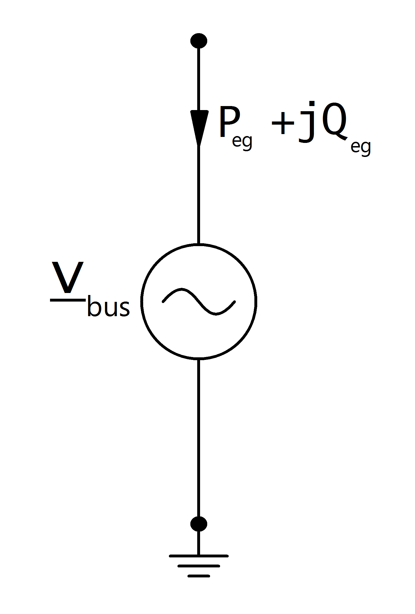
with:
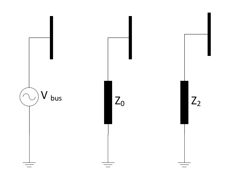
** Unbalanced Load Flow / Single phase short ciruit **
The external grid is modelled as a voltage source for positive sequence model, which means the node the grid is connected to is treated as a slack node. For zero sequence and negative sequence external grid impedance is calculated:
Result Parameters
net.res_ext_grid
Parameter |
Datatype |
Explanation |
p_mw |
float |
active power supply at the external grid [MW] |
q_mvar |
float |
reactive power supply at the external grid [MVar] |
Active and reactive power feed-in / consumption at the slack node is a result of the power flow:
net.res_ext_grid_3ph
Parameter |
Datatype |
Explanation |
p_a_mw |
float |
active power supply at the external grid : Phase A [MW] |
q_a_mvar |
float |
reactive power supply at the external grid : Phase A [MVar] |
p_b_mw |
float |
active power supply at the external grid : Phase B [MW] |
q_b_mvar |
float |
reactive power supply at the external grid : Phase B [MVar] |
p_c_mw |
float |
active power supply at the external grid : Phase C [MW] |
q_c_mvar |
float |
reactive power supply at the external grid : Phase C [MVar] |
Active and reactive power feed-in / consumption at the slack node is a result of the power flow: