Bus
See also
Create Function
Input Parameters
net.bus
Parameter |
Datatype |
Value Range |
Explanation |
name |
string |
name of the bus |
|
vn_kv* |
float |
\(>\) 0 |
rated voltage of the bus [kV] |
type |
string |
naming conventions:
“n” - node
“b” - busbar
“m” - muff
|
type variable to classify buses |
zone |
string |
can be used to group buses, for example network groups / regions |
|
max_vm_pu** |
float |
\(>\) 0 |
Maximum voltage |
min_vm_pu** |
float |
\(>\) 0 |
Minimum voltage |
in_service* |
boolean |
True / False |
specifies if the bus is in service. |
*necessary for executing a power flow calculation
**optimal power flow parameter
Note
Bus voltage limits can not be set for slack buses and will be ignored by the optimal power flow.
net.bus_geodata
Parameter |
Datatype |
Explanation |
x |
float |
x coordinate of bus location |
y |
float |
y coordinate of bus location |
Electric Model
Result Parameters
net.res_bus
Parameter |
Datatype |
Explanation |
vm_pu |
float |
voltage magnitude [p.u] |
va_degree |
float |
voltage angle [degree] |
p_mw |
float |
resulting active power demand [MW] |
q_mvar |
float |
resulting reactive power demand [Mvar] |
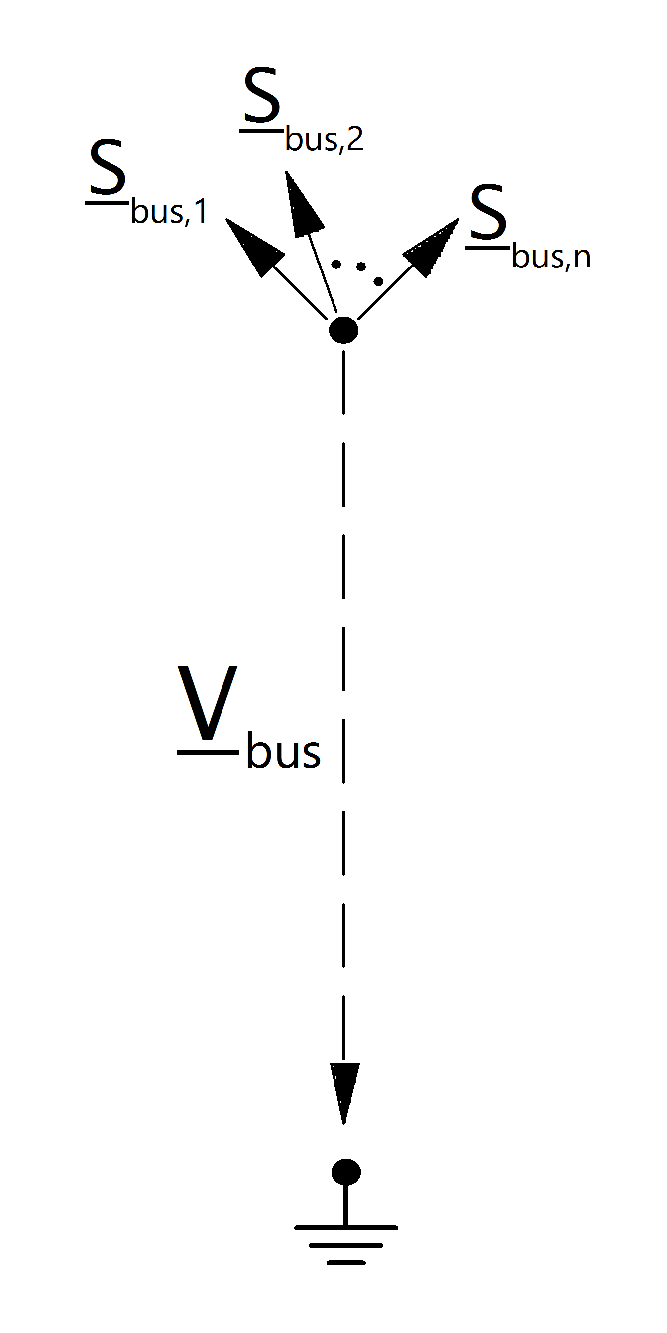
The power flow bus results are defined as:
net.res_bus_3ph
Parameter |
Datatype |
Explanation |
vm_a_pu |
float |
voltage magnitude:Phase A [p.u] |
va_a_degree |
float |
voltage angle:Phase A [degree] |
vm_b_pu |
float |
voltage magnitude:Phase B [p.u] |
va_b_degree |
float |
voltage angle:Phase B [degree] |
vm_c_pu |
float |
voltage magnitude:Phase C [p.u] |
va_c_degree |
float |
voltage angle:Phase C [degree] |
p_a_mw |
float |
resulting active power demand:Phase A [MW] |
q_a_mvar |
float |
resulting reactive power demand:Phase A [Mvar] |
p_b_mw |
float |
resulting active power demand:Phase B [MW] |
q_b_mvar |
float |
resulting reactive power demand:Phase B [Mvar] |
p_c_mw |
float |
resulting active power demand:Phase C [MW] |
q_c_mvar |
float |
resulting reactive power demand:Phase C [Mvar] |
unbalance_percent |
float |
unbalance in percent defined as the ratio of V0 and V1 according to IEC 62749 |
The power flow bus results are defined as:
net.res_bus_est
The state estimation results are put into net.res_bus_est with the same definition as in net.res_bus.
Parameter |
Datatype |
Explanation |
vm_pu |
float |
voltage magnitude [p.u] |
va_degree |
float |
voltage angle [degree] |
p_mw |
float |
resulting active power demand [MW] |
q_mvar |
float |
resulting reactive power demand [Mvar] |
Note
Bus power values are given in the consumer system. Therefore a bus with positive p_mw value consumes power while a bus with negative active power supplies power.