Three Winding Transformer
Create Function
-
pandapower.create_transformer3w(net, hv_bus, mv_bus, lv_bus, std_type, name=None, tap_pos=nan, in_service=True, index=None, max_loading_percent=nan, tap_at_star_point=False)¶ Creates a three-winding transformer in table net[“trafo3w”]. The trafo parameters are defined through the standard type library.
- INPUT:
net - The net within this transformer should be created
hv_bus (int) - The bus on the high-voltage side on which the transformer will be connected to
mv_bus (int) - The medium voltage bus on which the transformer will be connected to
lv_bus (int) - The bus on the low-voltage side on which the transformer will be connected to
std_type - The used standard type from the standard type library
- OPTIONAL:
name (string) - A custom name for this transformer
tap_pos (int, nan) - current tap position of the transformer. Defaults to the medium position (tap_neutral)
tap_at_star_point (boolean) - Whether tap changer is located at the star point of the 3W-transformer or at the bus
in_service (boolean) - True for in_service or False for out of service
index (int, None) - Force a specified ID if it is available. If None, the index one higher than the highest already existing index is selected.
max_loading_percent (float) - maximum current loading (only needed for OPF)
tap_at_star_point (bool) - whether tap changer is modelled at star point or at the bus
- OUTPUT:
- index (int) - The unique ID of the created transformer
- EXAMPLE:
- create_transformer3w(net, hv_bus = 0, mv_bus = 1, lv_bus = 2, name = “trafo1”, std_type = “63/25/38 MVA 110/20/10 kV”)
-
pandapower.create_transformer3w_from_parameters(net, hv_bus, mv_bus, lv_bus, vn_hv_kv, vn_mv_kv, vn_lv_kv, sn_hv_mva, sn_mv_mva, sn_lv_mva, vk_hv_percent, vk_mv_percent, vk_lv_percent, vkr_hv_percent, vkr_mv_percent, vkr_lv_percent, pfe_kw, i0_percent, shift_mv_degree=0.0, shift_lv_degree=0.0, tap_side=None, tap_step_percent=nan, tap_step_degree=nan, tap_pos=nan, tap_neutral=nan, tap_max=nan, tap_min=nan, name=None, in_service=True, index=None, max_loading_percent=nan, tap_at_star_point=False)¶ Adds a three-winding transformer in table net[“trafo3w”].
- Input:
net (pandapowerNet) - The net within this transformer should be created
hv_bus (int) - The bus on the high-voltage side on which the transformer will be connected to
mv_bus (int) - The bus on the middle-voltage side on which the transformer will be connected to
lv_bus (int) - The bus on the low-voltage side on which the transformer will be connected to
vn_hv_kv (float) rated voltage on high voltage side
vn_mv_kv (float) rated voltage on medium voltage side
vn_lv_kv (float) rated voltage on low voltage side
sn_hv_mva (float) - rated apparent power on high voltage side
sn_mv_mva (float) - rated apparent power on medium voltage side
sn_lv_mva (float) - rated apparent power on low voltage side
vk_hv_percent (float) - short circuit voltage from high to medium voltage
vk_mv_percent (float) - short circuit voltage from medium to low voltage
vk_lv_percent (float) - short circuit voltage from high to low voltage
vkr_hv_percent (float) - real part of short circuit voltage from high to medium voltage
vkr_mv_percent (float) - real part of short circuit voltage from medium to low voltage
vkr_lv_percent (float) - real part of short circuit voltage from high to low voltage
pfe_kw (float) - iron losses in kW
i0_percent (float) - open loop losses
- OPTIONAL:
shift_mv_degree (float, 0) - angle shift to medium voltage side*
shift_lv_degree (float, 0) - angle shift to low voltage side*
tap_step_percent (float) - Tap step in percent
tap_step_degree (float) - Tap phase shift angle in degrees
tap_side (string, None) - “hv”, “mv”, “lv”
tap_neutral (int, nan) - default tap position
tap_min (int, nan) - Minimum tap position
tap_max (int, nan) - Maximum tap position
tap_pos (int, nan) - current tap position of the transformer. Defaults to the medium position (tap_neutral)
tap_at_star_point (boolean) - Whether tap changer is located at the star point of the 3W-transformer or at the bus
name (string, None) - Name of the 3-winding transformer
in_service (boolean, True) - True for in_service or False for out of service
* only considered in loadflow if calculate_voltage_angles = True **The model currently only supports one tap-changer per 3W Transformer.
max_loading_percent (float) - maximum current loading (only needed for OPF)
- OUTPUT:
- trafo_id - The unique trafo_id of the created 3W transformer
- Example:
- create_transformer3w_from_parameters(net, hv_bus=0, mv_bus=1, lv_bus=2, name=”trafo1”, sn_hv_mva=40, sn_mv_mva=20, sn_lv_mva=20, vn_hv_kv=110, vn_mv_kv=20, vn_lv_kv=10, vk_hv_percent=10,vk_mv_percent=11, vk_lv_percent=12, vkr_hv_percent=0.3, vkr_mv_percent=0.31, vkr_lv_percent=0.32, pfe_kw=30, i0_percent=0.1, shift_mv_degree=30, shift_lv_degree=30)
Note
All short circuit voltages are given relative to the maximum apparent power flow. For example vk_hv_percent is the short circuit voltage from the high to the medium level, it is given relative to the minimum of the rated apparent power in high and medium level: min(sn_hv_mva, sn_mv_mva). This is consistent with most commercial network calculation software (e.g. PowerFactory). Some tools (like PSS Sincal) however define all short ciruit voltages relative to the overall rated apparent power of the transformer: max(sn_hv_mva, sn_mv_mva, sn_lv_mva). You might have to convert the values depending on how the short-circuit voltages are defined.
Input Parameters
net.trafo3w
| Parameter | Datatype | Value Range | Explanation |
| name | string | name of the transformer | |
| std_type | string | transformer standard type name | |
| hv_bus* | integer | high voltage bus index of the transformer | |
| mv_bus | integer | medium voltage bus index of the transformer | |
| lv_bus* | integer | low voltage bus index of the transformer | |
| vn_hv_kv* | float | rated voltage at high voltage bus [kV] | |
| vn_mv_kv* | float | \(>\) 0 | rated voltage at medium voltage bus [kV] |
| vn_lv_kv* | float | \(>\) 0 | rated voltage at low voltage bus [kV] |
| sn_hv_mva* | float | \(>\) 0 | rated apparent power on high voltage side [kVA] |
| sn_mv_mva* | float | \(>\) 0 | rated apparent power on medium voltage side [kVA] |
| sn_lv_mva* | float | \(>\) 0 | rated apparent power on low voltage side [kVA] |
| vk_hv_percent* | float | \(>\) 0 | short circuit voltage from high to medium voltage [%] |
| vk_mv_percent* | float | \(>\) 0 | short circuit voltage from medium to low voltage [%] |
| vk_lv_percent* | float | \(>\) 0 | short circuit voltage from high to low voltage [%] |
| vkr_hv_percent* | float | \(\geq\) 0 | real part of short circuit voltage from high to medium voltage [%] |
| vkr_mv_percent* | float | \(\geq\) 0 | real part of short circuit voltage from medium to low voltage [%] |
| vkr_lv_percent* | float | \(\geq\) 0 | real part of short circuit voltage from high to low voltage [%] |
| pfe_kw* | float | \(\geq\) 0 | iron losses [kW] |
| i0_percent* | float | \(\geq\) 0 | open loop losses [%] |
| shift_mv_degree | float | transformer phase shift angle at the MV side | |
| shift_lv_degree | float | transformer phase shift angle at the LV side | |
| tap_side | string | “hv”, “mv”, “lv” | defines if tap changer is positioned on high- medium- or low voltage side |
| tap_neutral | integer | ||
| tap_min | integer | minimum tap position | |
| tap_max | integer | maximum tap position | |
| tap_step_percent | float | \(>\) 0 | tap step size [%] |
| tap_step_degree | float | tap step size for voltage angle | |
| tap_at_star_point | bool | whether the tap changer is modelled at terminal or at star point | |
| tap_pos | integer | current position of tap changer | |
| in_service* | boolean | True/False | specifies if the transformer is in service. |
*necessary for executing a power flow calculation.
Note
Three Winding Transformer loading can not yet be constrained with the optimal power flow.
Electric Model
Three Winding Transformers are modelled by three two-winding transformers in \(Y\)-connection:
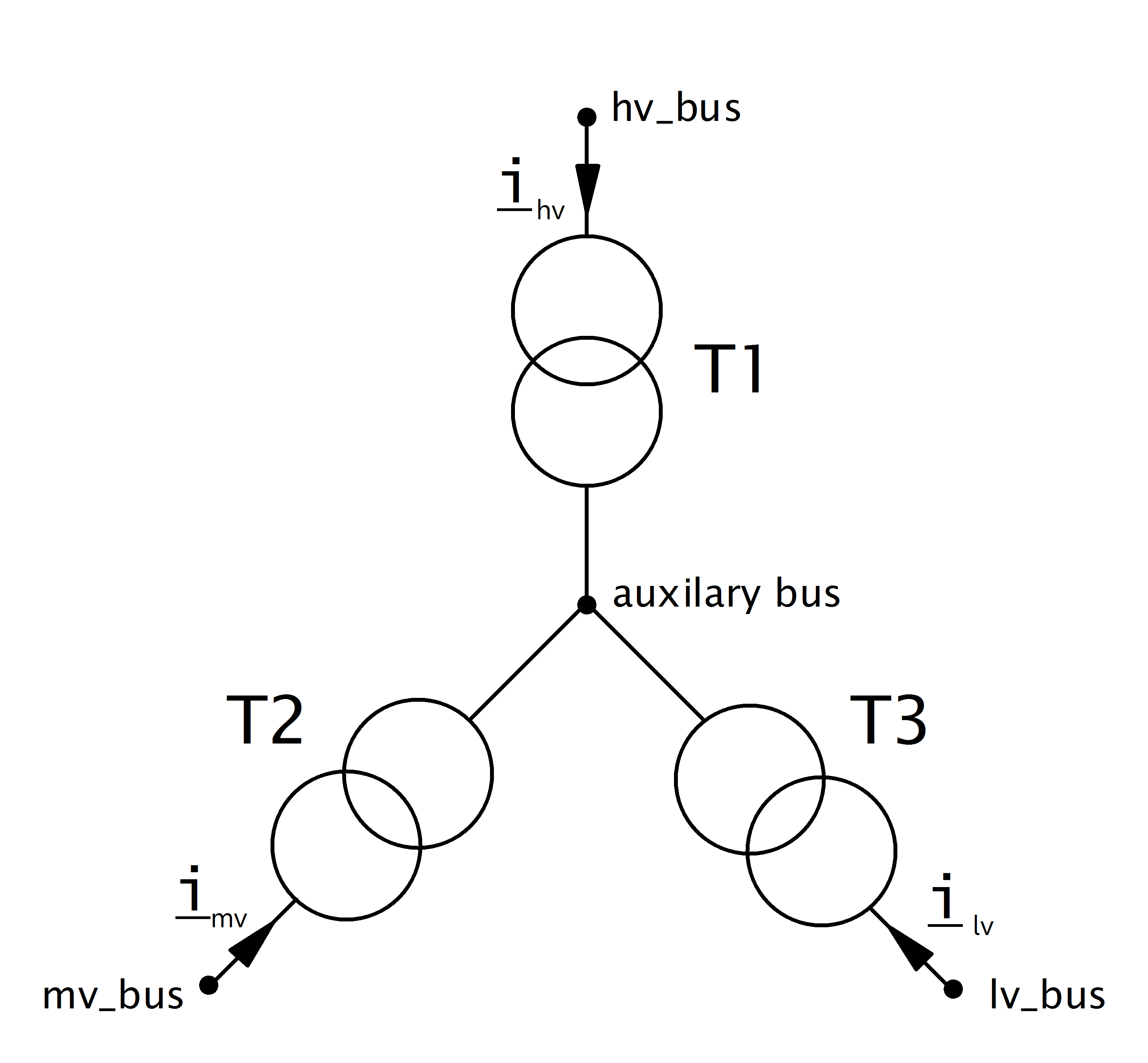
The parameters of the three transformers are defined as follows:
| T1 | T2 | T3 | |
| hv_bus | hv_bus | auxiliary bus | auxiliary bus |
| lv_bus | auxiliary bus | mv_bus | lv_bus |
| sn_mva | sn_hv_mva | sn_mv_mva | sn_lv_mva |
| vn_hv_kv | vn_hv_kv | vn_hv_kv | vn_hv_kv |
| vn_lv_kv | vn_hv_kv | vn_mv_kv | vn_lv_kv |
| vk_percent | \(v_{k, t1}\) | \(v_{k, t2}\) | \(v_{k, t3}\) |
| vkr_percent | \(v_{r, t1}\) | \(v_{r, t2}\) | \(v_{r, t3}\) |
| shift_degree | 0 | shift_mv_degree | shift_lv_degree |
The iron loss (pfe_kw) and open loop loss (i0_percent) of the 3W transformer is by default attributed to T1 (‘hv’). The parameter ‘trafo3w_losses’ in the runpp function however also allows to assign the losses to T2 (‘mv’), T3(‘lv’) or to the star point (‘star’).
To calculate the short-circuit voltages \(v_{k, t1..t3}\) and \(v_{r, t1..t3}\), first all short-circuit voltages are converted from side based values to branch based values
These transformer now represent a \(\Delta\) connection of the equivalent transformers. A \(\Delta-Y\) conversion is therefore applied to recieve the parameters in \(Y\)-connection:
Since these voltages are given relative to the high voltage side, they have to be transformed back to the voltage level of each transformer:
The real part of the short-circuit voltage is calculated in the same way.
The definition of how impedances are calculated for the two winding transformer from these parameters can be found here.
Note
All short circuit voltages are given relative to the maximum apparent power flow. For example vk_hv_percent is the short circuit voltage from the high to the medium level, it is given relative to the minimum of the rated apparent power in high and medium level: min(sn_hv_mva, sn_mv_mva). This is consistent with most commercial network calculation software (e.g. PowerFactory). Some tools (like PSS Sincal) however define all short circuit voltages relative to the overall rated apparent power of the transformer: max(sn_hv_mva, sn_mv_mva, sn_lv_mva). You might have to convert the values depending on how the short-circuit voltages are defined.
The tap changer adapts the nominal voltages of the transformer in the equivalent to the 2W-Model:
| tap_side=”hv” | tap_side=”mv” | tap_side=”lv” | |
| \(V_{n, HV, transformer}\) | \(vnh\_kv \cdot n_{tap}\) | \(vnh\_kv\) | \(vnh\_kv\) |
| \(V_{n, MV, transformer}\) | \(vnm\_kv\) | \(vnm\_kv \cdot n_{tap}\) | \(vnm\_kv\) |
| \(V_{n, LV, transformer}\) | \(vnl\_kv\) | \(vnl\_kv\) | \(vnl\_kv \cdot n_{tap}\) |
with
The variable tap_side controls if the tap changer is located at T1 (‘hv’), T2 (‘mv’) or T3 (‘lv’). The tap_at_star_point variable controls if the tap changer is located at the star point of the three winding transformer or at the terminal side (hv/mv/lv bus).
See also
Result Parameters
net.res_trafo3w
| Parameter | Datatype | Explanation |
| p_hv_mw | float | active power flow at the high voltage transformer bus [MW] |
| q_hv_mvar | float | reactive power flow at the high voltage transformer bus [kVar] |
| p_mv_mw | float | active power flow at the medium voltage transformer bus [MW] |
| q_mv_mvar | float | reactive power flow at the medium voltage transformer bus [kVar] |
| p_lv_mw | float | active power flow at the low voltage transformer bus [MW] |
| q_lv_mvar | float | reactive power flow at the low voltage transformer bus [kVar] |
| pl_mw | float | active power losses of the transformer [MW] |
| ql_mvar | float | reactive power consumption of the transformer [Mvar] |
| i_hv_ka | float | current at the high voltage side of the transformer [kA] |
| i_mv_ka | float | current at the medium voltage side of the transformer [kA] |
| i_lv_ka | float | current at the low voltage side of the transformer [kA] |
| loading_percent | float | transformer utilization [%] |
The definition of the transformer loading depends on the trafo_loading parameter of the power flow.
For trafo_loading=’current’, the loading is calculated as:
For trafo_loading=’power’, the loading is defined as: