Bus
See also
Create Function
-
pandapower.create_bus(net, vn_kv, name=None, index=None, geodata=None, type='b', zone=None, in_service=True, max_vm_pu=nan, min_vm_pu=nan, coords=None, **kwargs)¶ Adds one bus in table net[“bus”].
Busses are the nodes of the network that all other elements connect to.
- INPUT:
- net (pandapowerNet) - The pandapower network in which the element is created
- OPTIONAL:
name (string, default None) - the name for this bus
index (int, default None) - Force a specified ID if it is available. If None, the index one higher than the highest already existing index is selected.
vn_kv (float) - The grid voltage level.
geodata ((x,y)-tuple, default None) - coordinates used for plotting
type (string, default “b”) - Type of the bus. “n” - node, “b” - busbar, “m” - muff
zone (string, None) - grid region
in_service (boolean) - True for in_service or False for out of service
max_vm_pu (float, NAN) - Maximum bus voltage in p.u. - necessary for OPF
min_vm_pu (float, NAN) - Minimum bus voltage in p.u. - necessary for OPF
- coords (array, default None, shape= (,2L)) - busbar coordinates to plot the bus with multiple points.
- coords is typically a list of tuples (start and endpoint of the busbar) [(x1, y1), (x2, y2)]
- OUTPUT:
- index (int) - The unique ID of the created element
- EXAMPLE:
- create_bus(net, name = “bus1”)
Input Parameters
net.bus
| Parameter | Datatype | Value Range | Explanation |
| name | string | name of the bus | |
| vn_kv* | float | \(>\) 0 | rated voltage of the bus [kV] |
| type | string | naming conventions:
“n” - node
“b” - busbar
“m” - muff
|
type variable to classify buses |
| zone | string | can be used to group buses, for example network groups / regions | |
| max_vm_pu** | float | \(>\) 0 | Maximum voltage |
| min_vm_pu** | float | \(>\) 0 | Minimum voltage |
| in_service* | boolean | True / False | specifies if the bus is in service. |
*necessary for executing a power flow calculation
**optimal power flow parameter
Note
Bus voltage limits can not be set for slack buses and will be ignored by the optimal power flow.
net.bus_geodata
| Parameter | Datatype | Explanation |
| x | float | x coordinate of bus location |
| y | float | y coordinate of bus location |
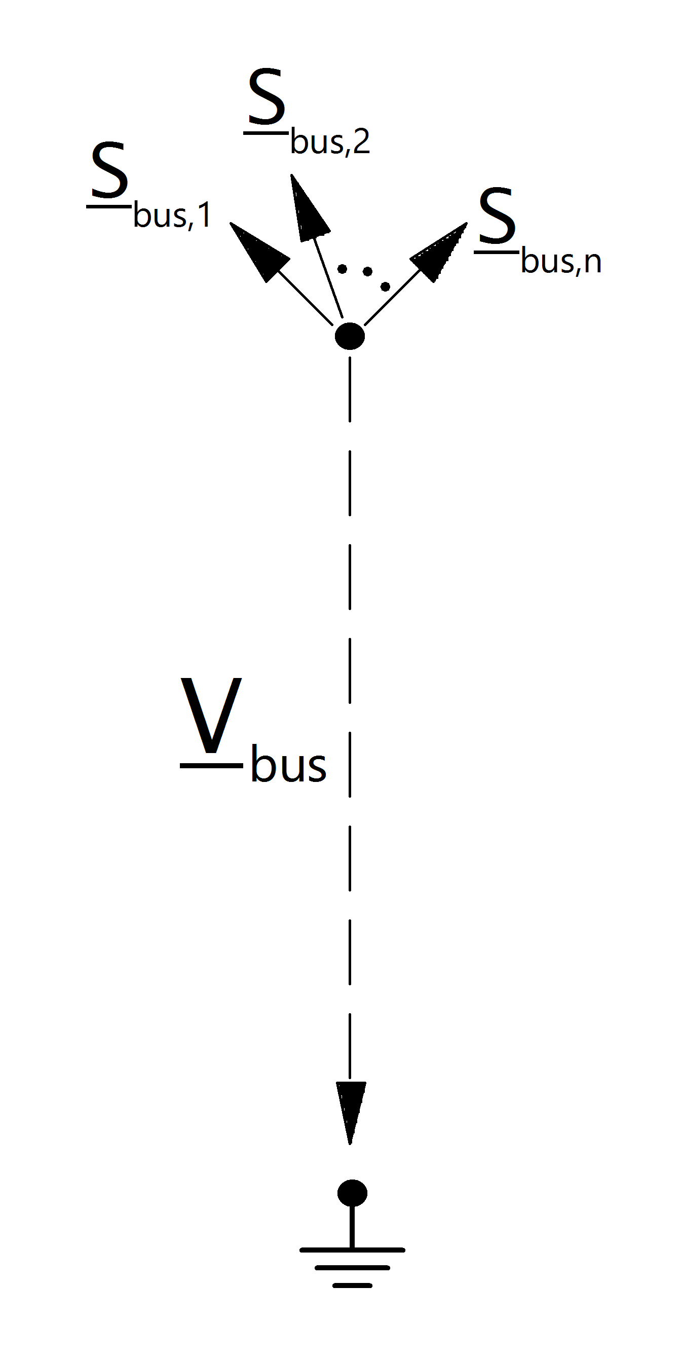
Electric Model
Result Parameters
net.res_bus
| Parameter | Datatype | Explanation |
| vm_pu | float | voltage magnitude [p.u] |
| va_degree | float | voltage angle [degree] |
| p_mw | float | resulting active power demand [MW] |
| q_mvar | float | resulting reactive power demand [Mvar] |
The power flow bus results are defined as:
net.res_bus_est
The state estimation results are put into net.res_bus_est with the same definition as in net.res_bus.
| Parameter | Datatype | Explanation |
| vm_pu | float | voltage magnitude [p.u] |
| va_degree | float | voltage angle [degree] |
| p_mw | float | resulting active power demand [MW] |
| q_mvar | float | resulting reactive power demand [Mvar] |
Note
Bus power values are given in the consumer system. Therefore a bus with positive p_mw value consumes power while a bus with negative active power supplies power.