Line
Create Function
Lines can be either created from the standard type library (create_line) or with custom values (create_line_from_parameters).
Note
Lines for 3 phase load flow uses zero sequence parameters which can be provided through a custom standard type using pandapower.create_std_type() and pandapower.add_zero_impedance_parameters()
Zero sequence parameters (Added through std_type For Three phase load flow) :
-r0_ohm_per_km (float) - zero sequence line resistance in ohm per km
-x0_ohm_per_km (float) - zero sequence line reactance in ohm per km
-c0_nf_per_km (float) - zero sequence line capacitance in nano Farad per km
- pandapower.create_line(net, from_bus, to_bus, length_km, std_type, name=None, index=None, geodata=None, df=1.0, parallel=1, in_service=True, max_loading_percent=nan, alpha=nan, temperature_degree_celsius=nan, **kwargs)
Creates a line element in net[“line”] The line parameters are defined through the standard type library.
- Parameters:
net (pandapowerNet) – The net within this line should be created
from_bus (int | integer) – ID of the bus on one side which the line will be connected with
to_bus (int | integer) – ID of the bus on the other side which the line will be connected with
length_km (float) – The line length in km
std_type (str) – Name of a standard line type: - Pre-defined in standard_linetypes - Customized std_type made using create_std_type()
name (str | None) – A custom name for this line
index (int | integer | None) – Force a specified ID if it is available. If None, the index one higher than the highest already existing index is selected.
geodata (Iterable[tuple[float, float]] | None) – Iterable[Tuple[int, int]|Tuple[float, float]], The geodata of the line. The first element should be the coordinates of from_bus and the last should be the coordinates of to_bus. The points in the middle represent the bending points of the line
in_service (bool) – True for in_service or False for out of service
df (float) – derating factor: maximum current of line in relation to nominal current of line (from 0 to 1)
parallel (int) – number of parallel line systems
max_loading_percent (float) – maximum current loading (only needed for OPF)
alpha (float) – temperature coefficient of resistance: R(T) = R(T_0) * (1 + alpha * (T - T_0))
temperature_degree_celsius (float) – line temperature for which line resistance is adjusted
- Keyword Arguments:
tdpf (bool) – whether the line is considered in the TDPF calculation
wind_speed_m_per_s (float) – wind speed at the line in m/s (TDPF)
wind_angle_degree (float) – angle of attack between the wind direction and the line (TDPF)
conductor_outer_diameter_m (float) – outer diameter of the line conductor in m (TDPF)
air_temperature_degree_celsius (float) – ambient temperature in °C (TDPF)
reference_temperature_degree_celsius (float) – reference temperature in °C for which r_ohm_per_km for the line is specified (TDPF)
solar_radiation_w_per_sq_m (float) – solar radiation on horizontal plane in W/m² (TDPF)
solar_absorptivity – Albedo factor for absorptivity of the lines (TDPF)
emissivity (float) – Albedo factor for emissivity of the lines (TDPF)
r_theta_kelvin_per_mw (float) – thermal resistance of the line (TDPF, only for simplified method)
mc_joule_per_m_k (float) – specific mass of the conductor multiplied by the specific thermal capacity of the material (TDPF, only for thermal inertia consideration with tdpf_delay_s parameter)
- Returns:
The unique ID of the created line
- Return type:
int | integer
Example
>>> create_line(net, from_bus=0, to_bus=1, length_km=0.1, std_type="NAYY 4x50 SE", name="line1")
- pandapower.create_line_from_parameters(net, from_bus, to_bus, length_km, r_ohm_per_km, x_ohm_per_km, c_nf_per_km, max_i_ka, name=None, index=None, type=None, geodata=None, in_service=True, df=1.0, parallel=1, g_us_per_km=0.0, max_loading_percent=nan, alpha=nan, temperature_degree_celsius=nan, r0_ohm_per_km=nan, x0_ohm_per_km=nan, c0_nf_per_km=nan, g0_us_per_km=0, endtemp_degree=nan, **kwargs)
Creates a line element in net[“line”] from line parameters.
- Parameters:
net (pandapowerNet) – The net within this line should be created
from_bus (int | integer) – ID of the bus on one side which the line will be connected with
to_bus (int | integer) – ID of the bus on the other side which the line will be connected with
length_km (float) – The line length in km
r_ohm_per_km (float) – line resistance in ohm per km
x_ohm_per_km (float) – line reactance in ohm per km
c_nf_per_km (float) – line capacitance (line-to-earth) in nano Farad per km
r0_ohm_per_km (float) – zero sequence line resistance in ohm per km
x0_ohm_per_km (float) – zero sequence line reactance in ohm per km
c0_nf_per_km (float) – zero sequence line capacitance in nano Farad per km
max_i_ka (float) – maximum thermal current in kilo Ampere
name (str | None) – A custom name for this line
index (int | integer | None) – Force a specified ID if it is available. If None, the index one higher than the highest already existing index is selected.
in_service (bool) – True for in_service or False for out of service
type (Literal['ol', 'cs'] | None) – type of line (“ol” for overhead line or “cs” for cable system)
df (float) – derating factor: maximum current of line in relation to nominal current of line (from 0 to 1)
g_us_per_km (float) – dielectric conductance in micro Siemens per km
g0_us_per_km (float) – zero sequence dielectric conductance in micro Siemens per km
parallel (int) – number of parallel line systems
geodata (Iterable[tuple[float, float]] | None) – The geodata of the line. The first row should be the coordinates of bus a and the last should be the coordinates of bus b. The points in the middle represent the bending points of the line
max_loading_percent (float) – maximum current loading (only needed for OPF)
alpha (float) – temperature coefficient of resistance: R(T) = R(T_0) * (1 + alpha * (T - T_0)))
temperature_degree_celsius (float) – line temperature for which line resistance is adjusted
endtemp_degree (float)
- Keyword Arguments:
tdpf – whether the line is considered in the TDPF calculation
wind_speed_m_per_s – wind speed at the line in m/s (TDPF)
wind_angle_degree – angle of attack between the wind direction and the line (TDPF)
conductor_outer_diameter_m – outer diameter of the line conductor in m (TDPF)
air_temperature_degree_celsius – ambient temperature in °C (TDPF)
reference_temperature_degree_celsius – reference temperature in °C for which r_ohm_per_km for the line is specified (TDPF)
solar_radiation_w_per_sq_m – solar radiation on horizontal plane in W/m² (TDPF)
solar_absorptivity – Albedo factor for absorptivity of the lines (TDPF)
emissivity – Albedo factor for emissivity of the lines (TDPF)
r_theta_kelvin_per_mw – thermal resistance of the line (TDPF, only for simplified method)
mc_joule_per_m_k – specific mass of the conductor multiplied by the specific thermal capacity of the material (TDPF, only for thermal inertia consideration with tdpf_delay_s parameter)
- Returns:
The unique ID of the created line
- Return type:
int | integer
Example
>>> create_line_from_parameters(net, from_bus=0, to_bus=1, length_km=0.1,
>>>   r_ohm_per_km=.01, x_ohm_per_km=0.05, c_nf_per_km=10, max_i_ka=0.4, name="line1"
>>> )
Input Parameters
net.line
Parameter |
Datatype |
Value Range |
Explanation |
name |
string |
name of the line |
|
std_type |
string |
standard type which can be used to easily define line parameters with the pandapower standard type library |
|
from_bus* |
integer |
Index of bus where the line starts |
|
to_bus* |
integer |
Index of bus where the line ends |
|
length_km* |
float |
\(>\) 0 |
length of the line [km] |
r_ohm_per_km* |
float |
\(\geq\) 0 |
resistance of the line [Ohm per km] |
x_ohm_per_km* |
float |
\(\geq\) 0 |
reactance of the line [Ohm per km] |
c_nf_per_km* |
float |
\(\geq\) 0 |
capacitance of the line (line-to-earth) [nano Farad per km] |
r0_ohm_per_km**** |
float |
\(\geq\) 0 |
zero sequence resistance of the line [Ohm per km] |
x0_ohm_per_km**** |
float |
\(\geq\) 0 |
zero sequence reactance of the line [Ohm per km] |
c0_nf_per_km**** |
float |
\(\geq\) 0 |
zero sequence capacitance of the line [nano Farad per km] |
g_us_per_km* |
float |
\(\geq\) 0 |
dielectric conductance of the line [micro Siemens per km] |
max_i_ka* |
float |
\(>\) 0 |
maximal thermal current [kilo Ampere] |
parallel* |
integer |
\(\geq\) 1 |
number of parallel line systems |
df* |
float |
0…1 |
derating factor (scaling) for max_i_ka |
type |
string |
Naming conventions:
“ol” - overhead line
“cs” - underground cable system
|
type of line |
max_loading_percent** |
float |
\(>\) 0 |
Maximum loading of the line |
endtemp_degree*** |
float |
\(>\) 0 |
Short-Circuit end temperature of the line |
in_service* |
boolean |
True / False |
specifies if the line is in service. |
geo |
string / object |
geojson.LineString object or its string representation |
*necessary for executing a balanced power flow calculation
**optimal power flow parameter
***short-circuit calculation parameter
****necessary for executing a three phase power flow / single phase short circuit
Note
Defining a line with length zero leads to a division by zero in the power flow and is therefore not allowed. Lines with a very low impedance might lead to convergence problems in the power flow for the same reason. If you want to directly connect two buses, please use the switch element instead of a line with a small impedance!
Electric Model
Lines are modelled with the \(\pi\)-equivalent circuit:
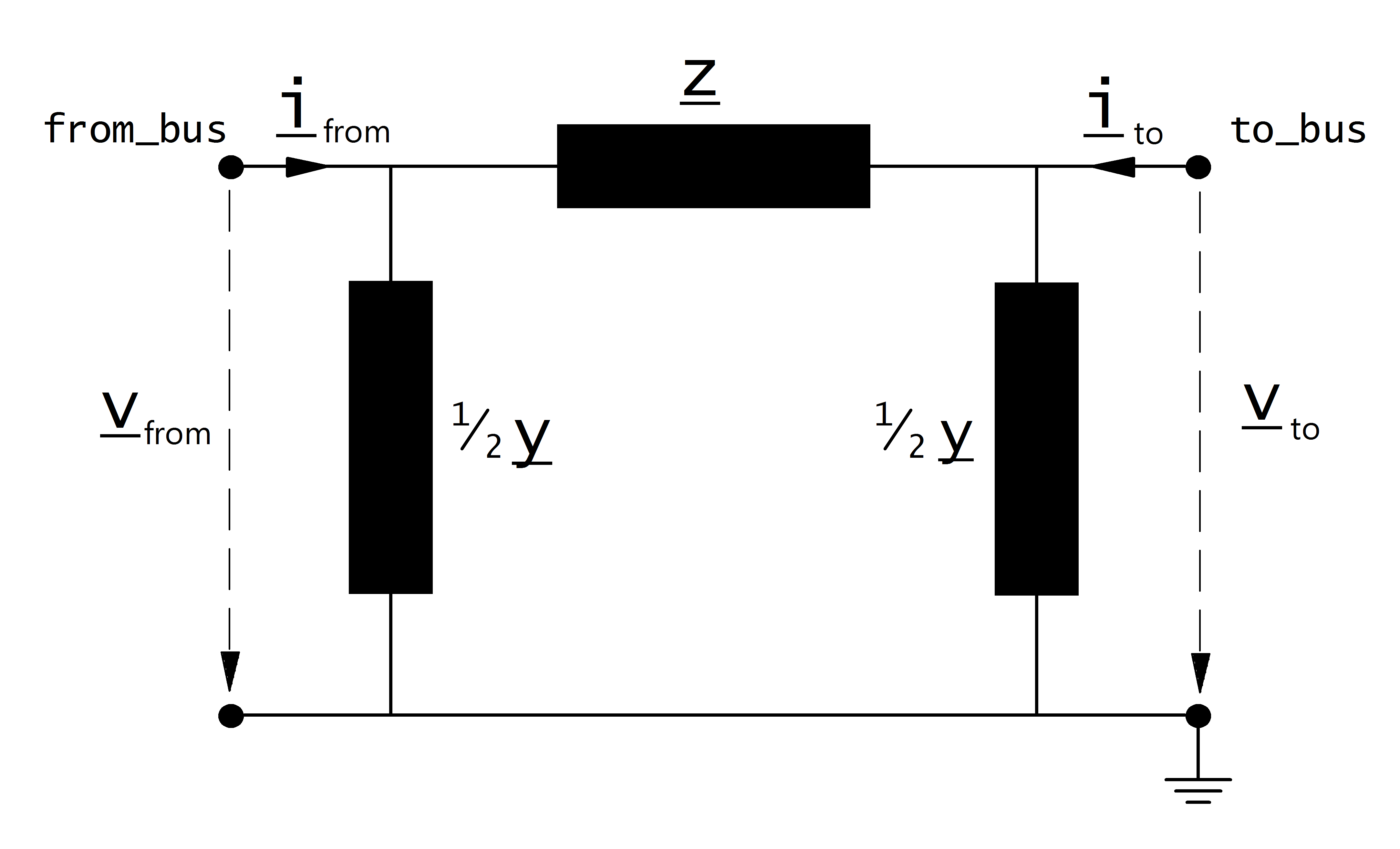
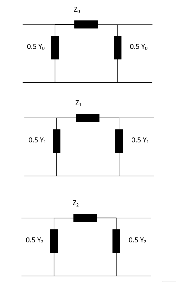
Three phase line model
The elements in the equivalent circuit are calculated from the parameters in the net.line dataframe as:
The power system frequency \(f\) is defined when creating an empty network, the default value is \(f = 50 Hz\).
Note
For three phase load flow, three decoupled sequence networks ( zero , positive and negative) are considered.
Positive and Negative sequence impedances are given by r_ohm_per_km, x_ohm_per_km, and c_nf_per_km
Zero sequence impedances are given by r0_ohm_per_km, x0_ohm_per_km, and c0_nf_per_km
The parameters are then transformed in the per unit system:
Where the reference voltage \(V_{N}\) is the nominal voltage at the from bus and the rated apparent power \(S_{N}\) is defined system wide in the net object (see Unit Systems and Conventions).
Note
pandapower assumes that nominal voltage of from bus and to bus are equal, which means pandapower does not support lines that connect different voltage levels. If you want to connect different voltage levels, either use a transformer or an impedance element.
Result Parameters
net.res_line
Parameter |
Datatype |
Explanation |
p_from_mw |
float |
active power flow into the line at “from” bus [MW] |
q_from_mvar |
float |
reactive power flow into the line at “from” bus [MVar] |
p_to_mw |
float |
active power flow into the line at “to” bus [MW] |
q_to_mvar |
float |
reactive power flow into the line at “to” bus [MVar] |
pl_mw |
float |
active power losses of the line [MW] |
ql_mvar |
float |
reactive power consumption of the line [MVar] |
i_from_ka |
float |
Current at from bus [kA] |
i_to_ka |
float |
Current at to bus [kA] |
i_ka |
float |
Maximum of i_from_ka and i_to_ka [kA] |
vm_from_pu |
float |
voltage magnitude at from bus |
vm_to_pu |
float |
voltage magnitude at to bus |
va_from_degree |
float |
voltage angle at from bus [degrees] |
va_to_degree |
float |
voltage angle at to bus [degrees] |
loading_percent |
float |
line loading [%] |
The power flow results in the net.res_line table are defined as:
net.res_line_3ph
Parameter |
Datatype |
Explanation |
p_a_from_mw |
float |
active power flow into the line at from bus: Phase A [MW] |
q_a_from_mvar |
float |
reactive power flow into the line at from bus : Phase A[MVar] |
p_b_from_mw |
float |
active power flow into the line at from bus: Phase B [MW] |
q_b_from_mvar |
float |
reactive power flow into the line at from bus : Phase B[MVar] |
p_c_from_mw |
float |
active power flow into the line at from bus: Phase C [MW] |
q_c_from_mvar |
float |
reactive power flow into the line at from bus : Phase C[MVar] |
p_a_to_mw |
float |
active power flow into the line at to bus: Phase A [MW] |
q_a_to_mvar |
float |
reactive power flow into the line at to bus : Phase A[MVar] |
p_b_to_mw |
float |
active power flow into the line at to bus: Phase B [MW] |
q_b_to_mvar |
float |
reactive power flow into the line at to bus : Phase B[MVar] |
p_c_to_mw |
float |
active power flow into the line at to bus: Phase C [MW] |
q_c_to_mvar |
float |
reactive power flow into the line at to bus : Phase C[MVar] |
pl_a_mw |
float |
active power losses of the line: Phase A [MW] |
ql_a_mvar |
float |
reactive power consumption of the line: Phase A [MVar] |
pl_b_mw |
float |
active power losses of the line: Phase B [MW] |
ql_b_mvar |
float |
reactive power consumption of the line: Phase B [MVar] |
pl_c_mw |
float |
active power losses of the line: Phase C [MW] |
ql_c_mvar |
float |
reactive power consumption of the line: Phase C [MVar] |
i_a_from_ka |
float |
Current at from bus: Phase A [kA] |
i_b_from_ka |
float |
Current at from bus: Phase B [kA] |
i_c_from_ka |
float |
Current at from bus: Phase C [kA] |
i_n_from_ka |
float |
Current at from bus: Neutral [kA] |
i_a_to_ka |
float |
Current at to bus: Phase A [kA] |
i_b_to_ka |
float |
Current at to bus: Phase B [kA] |
i_c_to_ka |
float |
Current at to bus: Phase C [kA] |
i_n_to_ka |
float |
Current at to bus: Neutral [kA] |
i_ka |
float |
Maximum of i_from_ka and i_to_ka [kA] |
loading_a_percent |
float |
line a loading [%] |
loading_b_percent |
float |
line b loading [%] |
loading_c_percent |
float |
line c loading [%] |
loading_percent |
float |
line loading in [%], is the maximum of all three phases |
The power flow results in the net.res_line_3ph table are defined as:
net.res_line_est
The state estimation results are put into net.res_line_est with the same definition as in net.res_line.
Parameter |
Datatype |
Explanation |
p_from_mw |
float |
active power flow into the line at “from” bus [MW] |
q_from_mvar |
float |
reactive power flow into the line at “from” bus [MVar] |
p_to_mw |
float |
active power flow into the line at “to” bus [MW] |
q_to_mvar |
float |
reactive power flow into the line at “to” bus [MVar] |
pl_mw |
float |
active power losses of the line [MW] |
ql_mvar |
float |
reactive power consumption of the line [MVar] |
i_from_ka |
float |
Current at from bus [kA] |
i_to_ka |
float |
Current at to bus [kA] |
i_ka |
float |
Maximum of i_from_ka and i_to_ka [kA] |
vm_from_pu |
float |
voltage magnitude at from bus |
vm_to_pu |
float |
voltage magnitude at to bus |
va_from_degree |
float |
voltage angle at from bus [degrees] |
va_to_degree |
float |
voltage angle at to bus [degrees] |
loading_percent |
float |
line loading [%] |
net.res_line_sc
The short-circuit (SC) results are put into net.res_line_sc with following definitions:
Parameter |
Datatype |
Explanation |
ikss_ka |
float |
initial short-circuit current value [kA] |
ikss_from_ka |
float |
magnitude of the initial SC current at “”from”” bus [kA] |
ikss_from_degree |
float |
degree of the initial SC current at “”from”” bus [degrees] |
ikss_to_ka |
float |
magnitude of the initial SC current at “”to”” bus [kA] |
ikss_to_degree |
float |
degree of the initial SC current at “”to”” bus [degrees] |
p_from_mw |
float |
active SC power flow into the line at “”from”” bus [MW] |
q_from_mvar |
float |
reactive SC power flow into the line at “”from”” bus [MVar] |
p_to_mw |
float |
active SC power flow into the line at “”to”” bus [MW] |
q_to_mvar |
float |
reactive SC power flow into the line at “”to”” bus [MVar] |
vm_from_pu |
float |
voltage magnitude at “”from”” bus [p.u.] |
vm_to_pu |
float |
voltage magnitude at “”to”” bus [p.u.] |
va_from_degree |
float |
voltage angle at “”from”” bus [degrees] |
va_to_degree |
float |
voltage angle at “”to”” bus [degrees] |
ip_ka |
float |
peak value of the short-circuit current [kA] |
ith_ka |
float |
equivalent thermal short-circuit current [kA] |