Grid Equivalent Module Overview
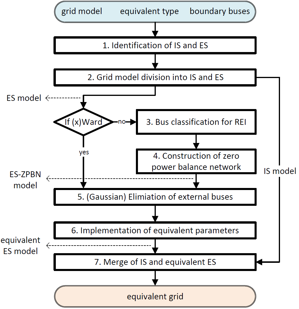
When calling the function get_equivalent() the calculation of an equivalent grid is started. During the calculation process, the internal subsystem (IS) and the external subsystem (ES) are considered separately. The following figure illustrates the flow chart for the implemented equivalent calculations.
As input variables, the grid model to be reduced with associated power flow results (in particular, the voltage values at the boundary buses. You can obtain the power flow results by pp.runpp()), the equivalent type (“ward”, “xward”, or “rei”), and the boundary buses with which IS and ES can be identified are required. The procedure can be described as follows:
Identification of IS and ES according to the inputs: all buses are classified into three groups: internal buses, boundary buses, and external buses.
Grid model division into IS model and ES model.
(If REI equivalent) Bus classification for REI: the external buses are further identified and classified for the construction of the zero power balance network (ZPBN).
(If REI equivalent) Construction of ZPBN: in default, loads and generators in ES are considered individually and separately during the aggregation, respectively.
Performing Gaussian Elimination: the external buses for Ward or REI equivalents are eliminated. Resulting from eliminations, the equivalent parameters are calculated.
Implementation of equivalent parameters: the equivalent devices are created according to the equivalent parameters, while the external buses are removed. The equivalent ES model is constructed.
Merge of the IS model and the equivalent ES model: the constructed equivalent ES model and the IS model are merged.