Voltage Source Elements
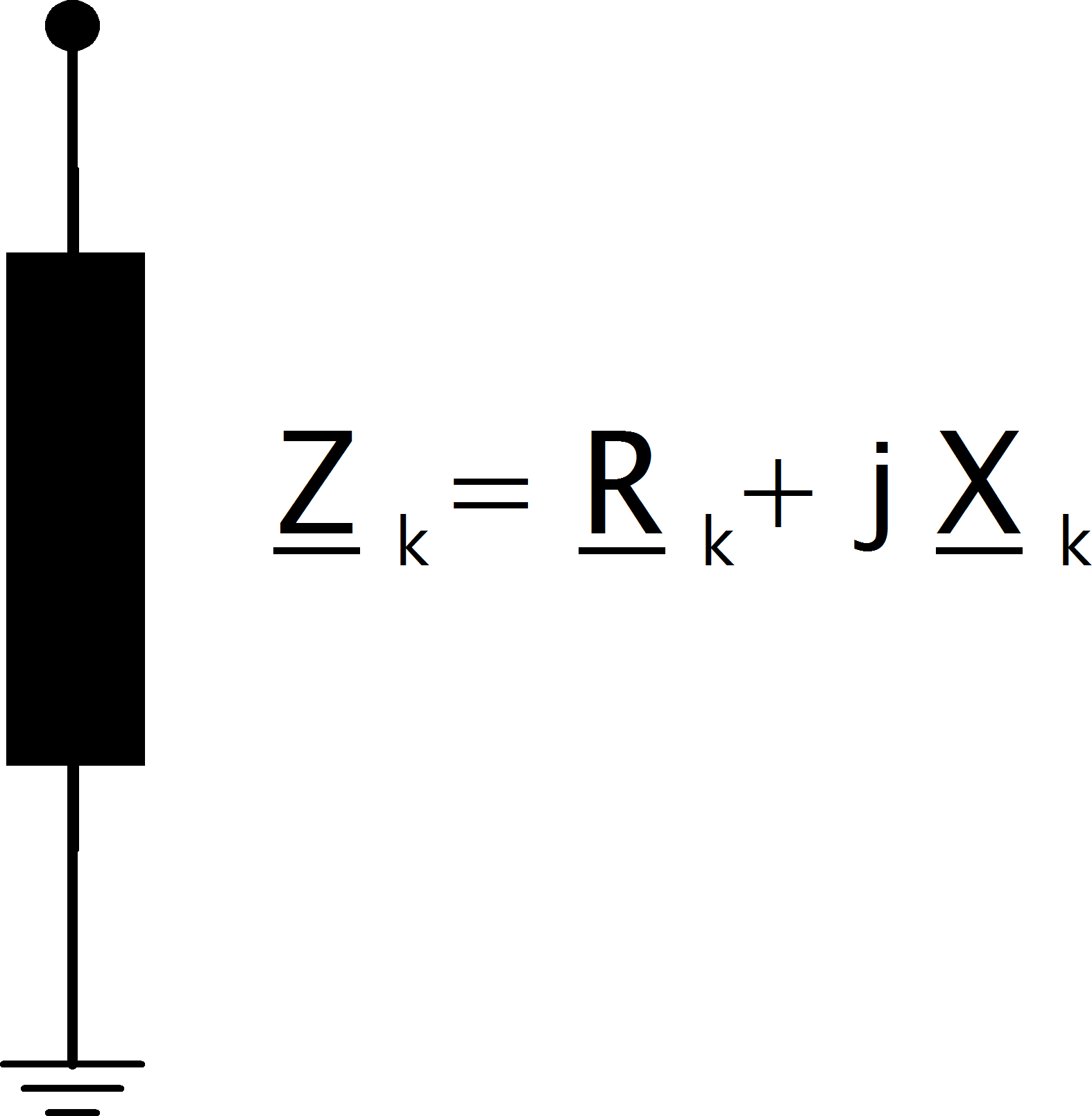
Voltage source elements are represented by their internal voltage source with an internal resistance \(Z_k\):
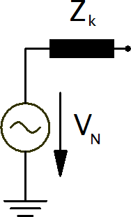
since the voltage source is moved to the fault location for with methodology of the equivalent voltage source, the bus elements can be reduced to a single shunt impedance:
The contribution of loads and shunts are negligible according to the standard and therefore neglected in the short-circuit calculation.
External Grid
When calculating maximum short-circuit currents, the impedance of an external grid connection is given as:
where \(rx\_max\) and \(s\_sc\_max\_mva\) are parameters in the ext_grid table and \(c_{max}\) is the voltage correction factor of the external grid bus.
In case of minimal short-circuit currents, the impedance is calculated accordingly:
Asynchronous Motor
Asynchronous motors can be considered by setting the type variable of an sgen element to “motor”. The internal impedance is then calculated as:
where \(sn\_kva\) is the rated power of the motor, \(k\) is the ratio of nominal to short circuit current and \(rx\) is the R/X ratio of the motor. \(vn\_kv\) is the rated voltage of the bus the motor is connected to.
Synchronous Generator
Synchronous generators are considered with the short-circuit impedance of:
The short-circuit impedance is calculated as:
The generator correction factor \(K_G\) is given as:
where \(V_{N, bus}\) is the rated voltage of the bus the generator is connected to and \(V_{N, gen}\) is the rated voltage of the generator which is defined by the parameter \(\text{sn\_kva}\) in the gen table. The rated phasor angle \(\varphi\) is given as:
where \(cos\_phi\) is defined in the gen table.